@Salas
I heard the left channel with less gain so come back to measurements:
(R=right channel & L=left channel)
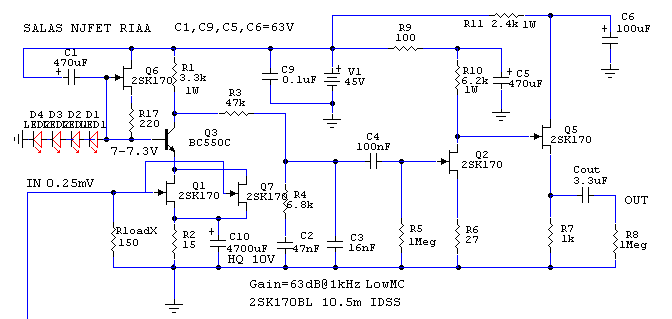
Leds/GND 7,22V(R) 7,24V(L)
R17 across 293mV(R) 278mV(L)
R10/Q2 to GND 9,94V (left channel changing values from 10V to 0,49V & when is low value the leds don't lit or shine less) it's possible Q2 damaged?
R1/Q3 to GND 12,24V(R) 12,08 (L)
R7/GND 10V both channels
Drain Q5 to GND 22,4V(R) 22,3V
Regulators current:
Right 415mA
Left 418mA
Thank in advance for kind help
I heard the left channel with less gain so come back to measurements:
(R=right channel & L=left channel)
Leds/GND 7,22V(R) 7,24V(L)
R17 across 293mV(R) 278mV(L)
R10/Q2 to GND 9,94V (left channel changing values from 10V to 0,49V & when is low value the leds don't lit or shine less) it's possible Q2 damaged?
R1/Q3 to GND 12,24V(R) 12,08 (L)
R7/GND 10V both channels
Drain Q5 to GND 22,4V(R) 22,3V
Regulators current:
Right 415mA
Left 418mA
Thank in advance for kind help
Last edited:
@Salas
To adjust balance between channels I want to change fixed resistor R2 15R for Vishay 1280G trimming potentiometers .75W, 15ppm, wich value will be enough: 20R, 50R?
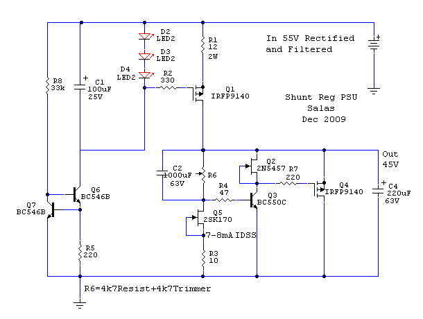
These two 5K are both for SSSLWR (super simplistic Salas low voltage regulator)
To adjust balance between channels I want to change fixed resistor R2 15R for Vishay 1280G trimming potentiometers .75W, 15ppm, wich value will be enough: 20R, 50R?
An externally hosted image should be here but it was not working when we last tested it.
These two 5K are both for SSSLWR (super simplistic Salas low voltage regulator)
Last edited:
Thanks, now I see. First change Q2. I don't like it shows different voltages. Maybe got some damage. If it will not match well after that for RMS out between channels, change both R6 for 50R trimmers and then you will be able to trim the gain. Stay over 27 Ohm.
If they are genuine items we can design for GR when not looking for top gain and MM lends for that. Try your hand on this one. Use an LM317 reg firstly just to see if the FETs behave as expected for gain & low noise. The 100k input load trimmer connected as a rheostat will let you calibrate tone, since the omnipresent 47k load for MM is a myth.
Hello Salas
I am in.
A personalized CCT and all. I am off to check my parts bins and match some pairs.
Thanks for the light.
DT
All just for fun!
Thanks, now I see. First change Q2. I don't like it shows different voltages. Maybe got some damage. If it will not match well after that for RMS out between channels, change both R6 for 50R trimmers and then you will be able to trim the gain. Stay over 27 Ohm.
Ok I will change Q2, I have just installed following your advice 50R trimmers (now I installed Vishay 1280G 15ppm 😉) I will stay over 27 ohms, I will let you know, thank you.
Wich one?
@Salas
I have these dual LSK389BL:
10,65 / 10,75
10,68 / 10,84
10,05 / 10,27
11,15 / 10,72
10,20 / 9,97
11,15 / 10,90
10,78 / 10,64
Wich one will be better to change damaged for 10,50 Idss?
@Salas
I have these dual LSK389BL:
10,65 / 10,75
10,68 / 10,84
10,05 / 10,27
11,15 / 10,72
10,20 / 9,97
11,15 / 10,90
10,78 / 10,64
Wich one will be better to change damaged for 10,50 Idss?
Intend to build this NJFET RIAA. I have about 30 transistors 2SK170BL. No idea about how to match them. Could you help me, please?
@Salas
Changed the njfet now all measurements are ok thank you🙂, to adjust balance between channels I want to change fixed resistor R2 15R for Vishay 1280G trimming potentiometers .75W, 15ppm, wich value will be enough: 20R, 50R?
Changed the njfet now all measurements are ok thank you🙂, to adjust balance between channels I want to change fixed resistor R2 15R for Vishay 1280G trimming potentiometers .75W, 15ppm, wich value will be enough: 20R, 50R?
You asked that in the previous page I think. I recommend a 50R trimmer instead of R6. Preferable than tweaking R2.
I have installed R6 50 ohms trimmer, it's the same way like R2: increasing value less gain & decreasing the value more gain?
Last edited:
I have installed R6 50 ohms trimmer, it's the same way like R2: increasing value less gain & decreasing the value more gain?
ref ohms🙂
1st only increase a little bit of gain left channel to balance channels (I can't hear noise in right channel)🙂
IDSS Testing
Hello All,
An interesting thing happened. I think that I will share it.
I bought 240 2SK170GR’s and set up a test jig to test the IDSS of each. I placed a 30 inch by 40 inch used construction drawing face down on the table with values for IDSS ma jotted down in 0.1ma steps. The jig was a plastic breadboard, momentary switch, digital 0-20ma panel meter and a 9 volt “transistor radio” battery. It took about 1 hour to test all the 2SK170’s.
First the piles of JFETS varied from 12 in a pile to none. The distribution was all over the place. A graph of the results would not be smooth or continuous.
The most interesting observation is this; I went back and retested the items close to the value I want to use in my project. Most of the tested values were less than by 0.1ma than they were the first time they were tested. The voltage of the 9 volt battery was also down by a few tenths as well.
The moral of the story is that the test voltage makes a difference. Not an ASTM / ANSI standard test. Perhaps a regulated voltage supply would be more consistent? Thoughts? What regulated voltage, 10?
DT
All just for fun!
- Home
- Source & Line
- Analogue Source
- Simplistic NJFET RIAA