FSP RAW PSU PCB
Dear all,
Does anyone have 1 Salas FSP raw PSU pcb to many that could sell me?
Thanks and happy listening.
Dear all,
Does anyone have 1 Salas FSP raw PSU pcb to many that could sell me?
Thanks and happy listening.
Test Points Pins
I'm waiting on some last minute components to finish; but I'm thinking ahead and wonder if anyone has installed test point pins to facilitate testing. I know from experience that you (should say I) can make a mess of a nice, populated pcb by constant prodding and poking at hard-to-get-at test points. I read that TP2 is the same as one of the leads of (I think) C3 - so that should be fine; but what about TP1, and maybe GND and V+. Any wisdom on that?
I'm waiting on some last minute components to finish; but I'm thinking ahead and wonder if anyone has installed test point pins to facilitate testing. I know from experience that you (should say I) can make a mess of a nice, populated pcb by constant prodding and poking at hard-to-get-at test points. I read that TP2 is the same as one of the leads of (I think) C3 - so that should be fine; but what about TP1, and maybe GND and V+. Any wisdom on that?
A loop of off cut from a resistor would be ideal.
It's the one thing I didn't do with my build and it was awkward trying to hold the dmm probes in place while trying to make adjustments.
It's the one thing I didn't do with my build and it was awkward trying to hold the dmm probes in place while trying to make adjustments.
That's good news, guess I was just unlucky 🙁The R-Core arrived in good condition. I will test it this weekend 🙂
Finally I can finish my project!!!
I'm waiting on some last minute components to finish; but I'm thinking ahead and wonder if anyone has installed test point pins to facilitate testing. I know from experience that you (should say I) can make a mess of a nice, populated pcb by constant prodding and poking at hard-to-get-at test points. I read that TP2 is the same as one of the leads of (I think) C3 - so that should be fine; but what about TP1, and maybe GND and V+. Any wisdom on that?
You can clip a crock on C3's signal input leg and another crock on some ground point, both connected to a dmm looking for 4V there instead of 3.6V between TP1-TP2. Its a perfectly valid measurement points and voltage value alternative to set it up equally well.A loop of off cut from a resistor would be ideal.
It's the one thing I didn't do with my build and it was awkward trying to hold the dmm probes in place while trying to make adjustments.
Make sure that the undersides of the PCBs are fully clean from flux residue. Flux can make a high impedance JFET gate unstable. If that one check proves unrelated check the voltages from drain pin to ground across all JFETs in case one has significantly different voltage than its sibling in the good channel so it draws different current and replace it. If nothing like that happens, try with another C3 in the left channel first just to make sure its not about a dud NOS USSR sample. Also the metal capacitors bodies should not be in contact to alternative size capacitor pads located underneath them
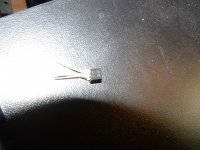
Checked jfets,, Q4 and Q5 on low volume side where both approx. 3.6 v on good board approx. 8.6 could not find any other volts that stood out so I changed both.The sound burst into life with perfect stereo very clear and its so good .The nos USSR caps are covered in clear heat shrink very hard to see in pic 😉 Thanks Salas
 Good. Having some clue on why they were so low on bias voltage? Were they possibly way off mark for proposed Idss or got too much time under the iron during assembly and developed a fault for instance?
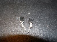
You are welcomeThat's hard to say ,I don't think it was heat ,,Q5 was 3.58v Q4 3.6v . as you can see both have same markings
This project gave me a tonnes of satisfaction, enjoyment ,I did learn a lot,,,thank you john
Those two you replaced them with have different font style print? Maybe like this?

Anyway, its nice to know you fixed the problem and you like it also. Happy listening!
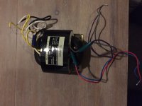
Just cheapo chassis transformers from FarnellGuess so! What are u using now for power?
Yes both different I have pic of spare one and the other is 170bl2j 🙂
This kind of print is more persuasive for being original. All well then. What's the rest of the system your FSP plays in by the way?
You can clip a crock on C3's signal input leg and another crock on some ground point, both connected to a dmm looking for 4V there instead of 3.6V between TP1-TP2. Its a perfectly valid measurement points and voltage value alternative to set it up equally well.
Thanks
I'm waiting on some last minute components to finish; but I'm thinking ahead and wonder if anyone has installed test point pins to facilitate testing. I know from experience that you (should say I) can make a mess of a nice, populated pcb by constant prodding and poking at hard-to-get-at test points. I read that TP2 is the same as one of the leads of (I think) C3 - so that should be fine; but what about TP1, and maybe GND and V+. Any wisdom on that?
Like this?

Would you measure primary and secondary resistances?Hi Simon,
The R-Core arrived in good condition. I will test it this weekend 🙂
Finally I can finish my project!!!
Kind regards,
Sjoerd
Can you measure the Iprimary vs Vprimary with no load on the secondary?
This kind of print is more persuasive for being original. All well then. What's the rest of the system your FSP plays in by the way?
Well I have some valve stuff,,amp is GSG from Diytube,Hagerman cornet,Pete millett low mu pre. Wanted to hear solid state to compare so I have only got ESP p101 amp,,Lenco gl85 with a Rega arm modded and a speed controller,my speakers are Mission 753 .I have some photos if you would like to see ?🙂
Well I have some valve stuff,,amp is GSG from Diytube,Hagerman cornet,Pete millett low mu pre. Wanted to hear solid state to compare so I have only got ESP p101 amp,,Lenco gl85 with a Rega arm modded and a speed controller,my speakers are Mission 753 .I have some photos if you would like to see ?🙂
Would that be a Nigel's speed controller for the Lenco?
- Home
- Source & Line
- Analogue Source
- Simplistic NJFET RIAA