It is interesting that the fellow who wrote the article
http://www.borbelyaudio.com/pics/waagbo2863.pdf
on Erno Borbely web site, has also built and tested opamp versions of mosfet regulators, similar topology to the one I built. He also reported something wrong with the sound of the opamp based one. I don't know, but I like the sound and performance on paper of the last one posted a little earlier. I think we have got here from the beginning, with your initial version, an excellent regulator. On paper these improvements may show, but in real life, perhaps also.
Loading R's for my Glider
Still trying to figure this out. The data on my Glider LO says load impedance- 120ohms. Ive tried various R values ( 500, 1k, 10k, 41k, 82k with PRP resistors) and found higher to my liking- though bit too relaxed in the highs. What I hear from others, no-one really loads theirs with anything that high.
So I need to try the Shinkoh's. But what value? Well, if I buy 3 2k4's per channel, I can series-parallel 6 values for each channel- 800, 1k2, 2k4, 3k6, 4k8, 7k2. A pretty good spread. Would doing this have any sonic penalty?
Thx- Kent
not so good you will add the noise from resistor.......
shinkoh is very 3d sound but little soft , try hight value , riken are for you ,the hight are live (too much for me)
150r riken have more live higth then 200r shinkoh (if I remember well!)
I like hight load, more sound stage ,big sound , but the sound start on bright side ,now you know why I like soft resistor 😉
ikoflexer said:Another detail which might help others: a ceramic 100nF capacitor right at the B+ and GND entrance to the njfet phono is a great improvement (high freq. filtering).
🙂 you are right , must do !
and one between the stage ....
salas said:This extra JFET CCS for the BJT we have checked out here too and we all got somewhat better sound, but Ricardo got the most subjective benefit. Maybe because he uses a cascode first stage. Its code name is ''R6 mod''.
For the 100nF directly on the B+ receiving end to gnd, I have to agree, the more the wire length from shunt to phono, the more work it does. I have recommended that to Ricardo and vgeorge. Always to be used when separate PSU and Phono boxes are employed. You can see it on mine too, where the red and black B+&GND twisted pair meets the phono board.
Here
Hi Salas
The R6 mod is very important... it makes the shunt sound much much better... it is not a subjective impression.
I will do the 100nf mod. (Did you use a russian cap there ?)
Ricardo
Re: Loading R's for my Glider
I experimented loading my Benz ACE mid output with 460r; 680r; 1k8; 2k2; 27k; 39k; and 47k.
Below 1k8 the sound is muted but the bass is very tight.
With 39k or 47k the spatiality is very good but the bass is loose.
I settled with 2k2 and am now using welwyn RY55 metal film... very good sound indeed.
Next step will be the shinkoh with 2k2 or 2k4. These tants add a lot of space and detail.
In your case I would search near 1k.
Ricardo
Hi Kentkstlfido said:Still trying to figure this out. The data on my Glider LO says load impedance- 120ohms. Ive tried various R values ( 500, 1k, 10k, 41k, 82k with PRP resistors) and found higher to my liking- though bit too relaxed in the highs. What I hear from others, no-one really loads theirs with anything that high.
So I need to try the Shinkoh's. But what value? Well, if I buy 3 2k4's per channel, I can series-parallel 6 values for each channel- 800, 1k2, 2k4, 3k6, 4k8, 7k2. A pretty good spread. Would doing this have any sonic penalty?
I experimented loading my Benz ACE mid output with 460r; 680r; 1k8; 2k2; 27k; 39k; and 47k.
Below 1k8 the sound is muted but the bass is very tight.
With 39k or 47k the spatiality is very good but the bass is loose.
I settled with 2k2 and am now using welwyn RY55 metal film... very good sound indeed.
Next step will be the shinkoh with 2k2 or 2k4. These tants add a lot of space and detail.
In your case I would search near 1k.
Ricardo
RCruz said:
I will do the 100nf mod. (Did you use a russian cap there ?)
Ricardo
Yes, a Ruskie PIO it is on the photo. (It is no mod, just a useful add on).
kstlfido said:
Salas- thanks. I'll wait on the corrections. Then we are all talking the same part #'s. I will try to design a matching shunt PCB (the R6 mod one) as well.
One thing I'd like to do is to make more room for bigger R's; namely the 2W Kiwame's you and others are using. What is the size of them? I do hate standing them on end- ugly! 😀
-Kent
Hi Kent.
I have started trying to get them together. Can you add pads for a 0.1uF bypass film cap right near to the B+ point on the phono board across to the GND too? Also a CxIn for those with MM version?
Kiwame:
Carbon Film
E-24 class
2W and 5W type, 750 volts DC max
+/-5% (actually +/-0.5%)
Silicon Resin
Light Green
2W (BODY) diameter-4.2mm, length-12mm. (LEAD) diameter-0.8mm, length-28mm
5W (BODY) diameter-9mm, length-24mm. (LEAD) diameter-0.8mm, length-36mm
Only with 2SK170GR or with a TO92 mini heatshink on your BC550C, because at that voltage of yours, it is going to dissipate 300mW if a BL takes it to 7.5mA constant current. BC 550C is a 500mW max little bug so I would not trust long time reliability in such use. (Some brands even say 625mW, but I would not go 50% to 75% max constantly and still feel its a good practice, plus the max gets limited a lot in a hotter than room ambient environment as in an amp or shunt PSU box). I would prefer a BL and the BC on T092 mini sink.
IMHO, the high freq bypass cap may be better monoblock ceramic, with very short leads, possibly best a surface mount. salas, are you sure about the pio bypass for high freq?
The PIO is good enough if there is around and the cables are not that long. Best would be a higher tec cap, but here is not like compensating a super fast op amp, we just add a drain for possible RF to ground. Whatever Kent finds good for his PCB size and easily available, will do. A Wima maybe.
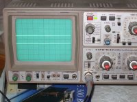
P.S. The noiseless scope line comparison (Ch1 shunt on phono without R6 mod VS CH2 scope's GND) was done without any RF cap at all, so no big worries, its just a good add on, given there is significant cable length and a strong enough RF field to pick up. So some will listen to a benefit and some will not.
Attachments
RCruz said:
Hi Salas
The R6 mod is very important... it makes the shunt sound much much better... it is not a subjective impression.
I will do the 100nf mod. (Did you use a russian cap there ?)
Ricardo
Hi Ricardo, as I told you before, you and others with a cascode first stage are the most benefited, because the cascode maybe offers more analysis, and of course it is mandatory in case of MM version for carts other than Grado, needing less input capacitance than the normal common source offers, but its PSRR will be the least offered. Also the RF cap maybe audible in your case too.
My scope trace without the bypass cap in place is about 2.5mV thick  and is reduced to thinner than GND trace when cap is used. Huge RF polution where I am, I guess 🙄 To each his own, but for people without a scope it makes sense to add a bypass cap. Can you think of any downsides to adding a small ceramic cap?
and is reduced to thinner than GND trace when cap is used. Huge RF polution where I am, I guess 🙄 To each his own, but for people without a scope it makes sense to add a bypass cap. Can you think of any downsides to adding a small ceramic cap?Yes, as I said, a prudent add on. Remember when I was warning you against external pick up, when you could not see it really thin?
For ceramic nothing against its tec HF merits, but every time I substituted such a b@gger for a fast PP cap it sounded less edgy. Either for a cart load or in PSU decoupling. So I avoid.
For ceramic nothing against its tec HF merits, but every time I substituted such a b@gger for a fast PP cap it sounded less edgy. Either for a cart load or in PSU decoupling. So I avoid.
Attachments
which sounded less edgy?salas said:........... every time I substituted such a b@gger for a fast PP cap it sounded less edgy........
ok I have gr and bl
but for negative rails I have only the 2sj74bl.....
I have dual to92 heatsink that I will use for the phono as Erno like a hot jfet😉 ,but JC report that at 24V the 2sj74 is .....
Vishay MKP 1837 for b+
but for negative rails I have only the 2sj74bl.....
I have dual to92 heatsink that I will use for the phono as Erno like a hot jfet😉 ,but JC report that at 24V the 2sj74 is .....
Vishay MKP 1837 for b+

- Home
- Source & Line
- Analogue Source
- Simplistic NJFET RIAA