Andrew. 211mA-60mA = 151mA or 140mA if you allow for control current. I was looking for an easy way to measure it vs. calculating it.
Salas, Let me make sure my understanding is correct. No assumptions here. Q1(irf9610) is the CCS fet. Q4(irfp9140) sets the voltage. If so, what is interesting is that as I ramp up the Vin, the current will stay <70mA until it hits the regulation voltage. At that point it jumps to 215mA. If I understand the circuit, Q1 is full on and Q4 is off till it has enough voltage headroom to regulate.
Salas, Let me make sure my understanding is correct. No assumptions here. Q1(irf9610) is the CCS fet. Q4(irfp9140) sets the voltage. If so, what is interesting is that as I ramp up the Vin, the current will stay <70mA until it hits the regulation voltage. At that point it jumps to 215mA. If I understand the circuit, Q1 is full on and Q4 is off till it has enough voltage headroom to regulate.
The voltage is set by the Vref which is the translation of current through a resistor by a Jfet CCS. The main CCS references to Vout in this, hence it won't open properly until you get the expected voltage conditions. If it will turn on instantly without a variac it should pull instantly too.
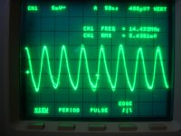
I put .1uF mkp on Vin. Big change but not a solution. Frequency jumped to 14mHz and is a cleaner sawtooth. See before and after in attached.
I have to pull board off of heat sink to implement change on gate resistor. (will do however if proper next step)
I also measured Vref across LED as 1.92V
I have to pull board off of heat sink to implement change on gate resistor. (will do however if proper next step)
I also measured Vref across LED as 1.92V
Attachments
Last edited:
Reinforces my suspicions that the resonance resides in the CCS. Make that 0.1uF a 47uF local decoupler, so we see where it goes, maybe some nH from layout resonates with something. Lets see about the gate stopper and possibly the base stopper values around the Mosfet and its control element next. Is the input voltage pre filtered BTW?
The power supply is the power supply used on V1. SInce it is seperate now, it was an easy thing to bring it back to my bench and use it. Rcore 2x18V through a CLC filter.
I will install the parallel gate stopper resistor now. Be back in a few.
I will install the parallel gate stopper resistor now. Be back in a few.
So there is a long shielded cable carrying Vin to the board. Make that Vin local decoupler in that 33uF you just tried elsewhere, so we see what changes.
With parallel 120R to make 60R for R3 no change. Vin decoupler still has same effect.
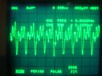
BTW please take Vpp and Vrms from scope and multiply by 10x. Had the probe in 10x configuration. At 1x I am seeing 80mVrms. 13MHz
BTW please take Vpp and Vrms from scope and multiply by 10x. Had the probe in 10x configuration. At 1x I am seeing 80mVrms. 13MHz
Last edited:
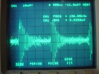
The lytic decouple at the output did reduce what appeared to be higher order harmonics, but did not have the impact the the mkp did on Vin. I will re-install the lytic Vout decoupler and report back.
80mV is too much, its oscillation. Lets see, can we move the compensation from the error amp nearer to the CFP? 9140 has 140pF Crss when 9240 has 81pF. We can be having a resonance there that can be read across the reg. I have done that once when I had to use a more capacitive shunt Mosfet because I was out of 9240.
Attachments
The lytic decouple at the output did reduce what appeared to be higher order harmonics, but did not have the impact the the mkp did on Vin. I will re-install the lytic Vout decoupler and report back.
I was asking what happens if using the lytic instead of the 0.1u at Vin.
Don't do that, its either a film Zobel or a normal ESR chemical cap. Things show the problem isn't the termination for now. It just went cuckoo with both.
Tried the lytic on the input. Same as the mkp. Rest of circuit as designed except for gate stopper at 60R
Something is not right for sure. So the 0.1uF is good enough value across the input, I use it too sometimes. Look at my post about moving and changing the compensation scheme.
P.S. To get it right, you never saw a straight line on the scope, yes? It was a sonar ping there on all knob settings?
P.S. To get it right, you never saw a straight line on the scope, yes? It was a sonar ping there on all knob settings?
With it regulating, I never saw a straight line. I only see the sonar ping with the lytic on the output. Without the lytic on Vout it is a steady state oscillation. I should clarify the cap on Vin makes it SS oscillation closest to sine wave.
Darn. Just blew the semi's again. I accidentally unplugged Vin. Won't start-up now.
Darn. Just blew the semi's again. I accidentally unplugged Vin. Won't start-up now.
With it plugged in, I watched the output voltage slowly climb until it hit regulation voltage. The LED lit up and away it went working again. Will set voltage fine, but still has HF oscillation just like before.
The error amp is a BC546B rated for 65Vceo and 85Vcbo
The error amp is a BC546B rated for 65Vceo and 85Vcbo
Last edited:
Its not normal, its struggling with some oscillation. If when touching with a probe the 9610's gate it will go on fast, its sure sign the oscillation upsets it. Try my post #4830. Its a thing that has a chance over revising the layout which will involve a lot of guess work. It does not change performance.
- Home
- Source & Line
- Analogue Source
- Simplistic NJFET RIAA