Thanks. Verifies my sketches as well. Magic smoke is goo din this case as it is obvious which is bad. It is when they go quitely that they drive a person nuts.
Now you see why I recommend V1 for starting and having a phono, when I recommend V1.2 for later on. Start clean slate by changing all semis if you will not debug fast.
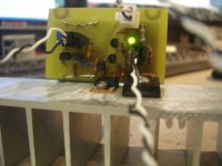
Completely. I can now get LED to light up sometimes, but will not regulate. The shunt irfp9140 FET is not conducting. Will put new semi's in it tomorrow. Have to go to game tonight.
Have your trimmer low value when firing up with new semis and be sure its connected like a rheostat too. Good luck tomorrow.
Repopulated Semi's twice now. Both times the board lit up and started to regulate. The first time I unplugged it and it never lit up again. The second time I ramped down the voltage using the variac. It is surviving. Need to understand why. Unloaded the PS produces 62Vdc.
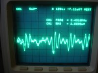
Loaded the PS is producing 55V filtered DC into the regulator. It regulates well at 42VDC out, however, I have some noise on the output. ABout 3mVrms in the MHz region. see attached. I think that part of my problem is I am only using twisted wire for the sense. I will replace that shortly.
Nothing is getting hot, just a comfortable warm.
Attachments
Repopulated Semi's twice now. Both times the board lit up and started to regulate. The first time I unplugged it and it never lit up again. The second time I ramped down the voltage using the variac. It is surviving. Need to understand why. Unloaded the PS produces 62Vdc.
Loaded the PS is producing 55V filtered DC into the regulator. It regulates well at 42VDC out, however, I have some noise on the output. ABout 3mVrms in the MHz region. see attached. I think that part of my problem is I am only using twisted wire for the sense. I will replace that shortly.
Nothing is getting hot, just a comfortable warm.
Congratulations

Don't forget the coaxial for remote sense could you use a small one RG179 type
700R which is 60mA, which slightly higher than the 50mA listed. Only R I had with enough wattage in that range.
See about the shielded cable first, I don't like the high MHz noise thing, see if it changes it, else it points to possible problems. It must be made stable for on/off without any variac also. What is the error amp load fet? Still 5459?
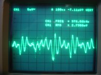
Shielded cable for sense actually increased resonance. Now at 4mVrms and in the 4-8mHz region. Error amp is 2N5457 with Idss of 2.5mA.
Watching th scope as I bring the voltage up, I see low level noise <<1mVrms untill it starts to regulate. At 42V the trace shows it starting to oscillate in the MhZ region at the levels described above.
P.S. Corrected units on Idss
Watching th scope as I bring the voltage up, I see low level noise <<1mVrms untill it starts to regulate. At 42V the trace shows it starting to oscillate in the MhZ region at the levels described above.
P.S. Corrected units on Idss
First test, rise the value of the mica comp cap and see what happens. If it will not behave better, second test is disconnect the termination Zobel on its one side and terminate with a 47uF not special type cap. Normal ESR.
No change at 100% and 200% (66pF and 99pF). I measured off of my scope. Fundemental resonance is 4.8mHz with higher order harmonics spread into it. Fundemental is 25mVpp
I will try the zobel next. When you say termination I assume you mean to ground. If I understand, you want me to run a 47uF across output.
I will try the zobel next. When you say termination I assume you mean to ground. If I understand, you want me to run a 47uF across output.
Last edited:
Its not the phase margin then. Something resonates. See about the termination now. Else its in the CCS. Disconnect the Zobel on its one side, and terminate with 47u across force out.
Hi,
you are drawing 60mA, 42Vdc & 700r.
What is the CCS passing and what is the Shunt passing?
you are drawing 60mA, 42Vdc & 700r.
What is the CCS passing and what is the Shunt passing?
Good question Andrew, I will measure CCS current in a minute. I can't easily measure shunt current however.
I put 33uF standard ESR in for Zobel with minimal impact. freq the same, less harmonic spread however. I will put the zobel back in and measure current.
I put 33uF standard ESR in for Zobel with minimal impact. freq the same, less harmonic spread however. I will put the zobel back in and measure current.
Shunt current = CCS current - [load current + quiescent current of the control circuit]
Allow ~10mA of control circuit current.
Allow ~10mA of control circuit current.
Good question Andrew, I will measure CCS current in a minute. I can't easily measure shunt current however.
I put 33uF standard ESR in for Zobel with minimal impact. freq the same, less harmonic spread however. I will put the zobel back in and measure current.
Minimal impact there with such a decisive change in the termination type and value makes me suspicious for a CCS resonance. If it was simply noise should have changed a lot or gone. Parallel one resistor on CCS Mosfet's gate stopper, so it goes half value. Changes something? Also does the decoupler on Vin affects? VR1/R1=CCS current BTW.
- Home
- Source & Line
- Analogue Source
- Simplistic NJFET RIAA