Output cap bypass
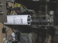
As you might know, I have been experimenting with some cap bypass..... The output caps are obbligato gold 4,7u and I connected some 100n FT-3 in parallel.
For this purpose I connected the bypass caps using aligator clips on long wires and did like the trebble and bass extension.
After some weeks I decided to hardwire and glued the FT-3 on the obbligatos and used some short silver wire to solder them im place.
There are enormous gains in attack and trebble extension but I did not like to overall result.... lost some mid freq presence and got some high freq coarseness.
Now I reverted to the no bypass situation and I am very pleased.
It seems the short wires killed the magic.
Another issue: As the bypass caps where glued to the main caps, and these are not fixed with braces, the contraption became very susceptible to microphony so I could not use the riaa without the lid closed..... All caps must be braced.
Ricardo
Salas said:2. Medium MC 1mV.
Hi Salas
I am now gathering parts to build my second riaa for the DL160.
I will use the schematic you posted in post 1813 http://www.diyaudio.com/forums/showthread.php?postid=1839225#post1839225
Due to my actual cost avoidance posture, I need to use whatever I have at home.
Can I use a 2x18v TX (instead of 2x15v) to power the 28v shunt ?
Can you please remind me the best Idss to use in Q1 Q2 and Q5 ?
Also, what is the best load for the DL160 ?
Regards
Ricardo
I use 45dB gain and 1k load for my 160. It can drive OK a B1 or my 6V6 buffer for circa 30dB amps into 95dB speakers. 48dB will pick up on the volume control soon if their is more than 6dB gain in your pre and the speakers are over 90dB, but on the other hand it is still controllable and good for SNR.
2X18V Trafo you want to use for double bridges and each 18V for a different shunt per channel? If yes, it is low. Will give about 24V DC for each, when you need 33V as lower safe for logical mains variations.
If you want to use it as a 36V single transformer, then you get about 50V and RC can take it down to 35V and will filter some mains and rectification gremlins also.
8.5mA Idss is the reference for Q1,2,5. You must know that by having a distortion meter or FFT, it is better if you can tune with trimmers instead of directly using steady Rs. Jfets differ in some things and there is always a sweeter spot for best THD in each build, and its clearly audible, but it takes some calibrated clean card or lab stuff. Another approach (practical but tedious) is to listen for +/- 0.5V Vd steps around ballpark Rs schematic value and decide. It changes Ibias, varies second harmonic and its proportion to 3rd. For the cascode stage you measure Vc on the bjt's top. Doing it by ear its a juggling act so to ''tune'' for two stages, but it is rewarding. Don't choke the stages for too low voltage across the elements or too little current.
Thank you Salas
I am using the TX to make 36v..... what type of RC do you suggest to lower the voltage ? (A resistor before the smoothing cap in the psu ?)
Ricardo
I am using the TX to make 36v..... what type of RC do you suggest to lower the voltage ? (A resistor before the smoothing cap in the psu ?)
Ricardo
RCruz said:Thank you Salas
I am using the TX to make 36v..... what type of RC do you mean to lower the voltage ?
Ricardo
36Vac X 1,4 == 50,4Vdc minus 2V drop in bridge should deliver 48Vdc on your reservoir capacitor. Each phono stage consumes about 50mA, so two will draw 0,1A. According to Ohm's law delta V (48-32)= 16Vdc which equals the current (0.1A) times the value of the drop resistor. So you need a 160 ohm resistor which dissipates 1,6 watt continiously. A 5W wirewound will be practical, followed by a capacitor as big or bigger than the reservoir cap. 2200uF 63V is a practical value.
Hi jaap
I do not want to use any cap after the smoothing cap... is that possible ?
In my working riaa, I am using a 2x15v TX (80VA) and I read 42v after the smoothing caps.... The shunts produce 28v from those 42v.... maybe that is why they heat so much ??
ricardo
I do not want to use any cap after the smoothing cap... is that possible ?
In my working riaa, I am using a 2x15v TX (80VA) and I read 42v after the smoothing caps.... The shunts produce 28v from those 42v.... maybe that is why they heat so much ??
ricardo
RCruz said:Hi jaap
I do not want to use any cap after the smoothing cap... is that possible ?
In my working riaa, I am using a 2x15v TX (80VA) and I read 42v after the smoothing caps.... The shunts produce 28v from those 42v.... maybe that is why they heat so much ??
ricardo
Yes mate, too much power is heating things up.
To get 32 to 33Vdc you better look for a 24V + 24V tranny in the 100 to 150W range. Nice, old skool EI-core is fine. Use a toroid if you must.
Re: Thanks for helps Salas
Good listening buddy. Enjoy.
nicoch46 said:the biker is back with Tube bombs😀 😀
Good listening buddy. Enjoy.
Keep in mind that due to the charging angle, in practice I have seen RC in that point (R to main filter cap) overshooting and needed to be lower than calculated. I would get 150R 5W, 120R 5W and 100R 5W, and see which one gets me where I want (7-8V Vdif in-out).
Salas
So if I use a 150w before the smoothers should I expect a reduction from 50v to 33 ?
I am considering this solution so I can use the small TX I got (2x18v 50 va)... 50v - 8v = 42v... does that mean that my working riaa sounds so good due to the excess of power ?
So if I use a 150w before the smoothers should I expect a reduction from 50v to 33 ?
I am considering this solution so I can use the small TX I got (2x18v 50 va)... 50v - 8v = 42v... does that mean that my working riaa sounds so good due to the excess of power ?
It will depend basically on Ohm's law for voltage drop, but be equipped with 120R and 100R as well, as I said because of different charging angles given the main cap's value and chosen Iccs, I have experienced deviations of dropping more than expected for resistor input RC filter & V dropper. That is if you draw 100mA total as assumed by Jaap. But you don't draw what the 2 phono channels need. You draw what the shunt(s) runs. So you calculate accordingly. Your 8V dif helps the shunt to work as intended. Your Riaa sounds so good because you put much care in to tuning it.
Hi Salas
I found another TX : 2 x 25v 80VA..... Maybe this is better and I will not need to reduce the voltage. What is your oppinion ?
I am also searching for shinkoh resistors... I will use one 1k for the DL160 load and another 47k for R3.... All other resistors will be takman carbon 0,5w . Is this a wise choice ?
Ricardo
PS: I was considering cutting costs but can not resist the high quality approach.
Wise choice both on trafo and resistors. I have them resistors chosen such in a 56dB build. Don't forget the trimmer thing I posted about fine tuning, since you are our official tweaker. 100R trimmer parallel to 100R resistor for Rsource. After tuning I get 0.0025% THD and 0.005% IMD with 0.5mV RMS input. Nice for a non loop feedback simplistic circuit. Check out FFT.
Attachments
I will not forget the trimmer..... Just need a little more info regarding it´s position on the schematic...
It's technically possible.RCruz said:I do not want to use any cap after the smoothing cap... is that possible ?
But why?
You are throwing out the potential to improve the sound quality of all subsequent stages by adopting this "ostrich" philosophy.
Because I am using some left over 15000uF Nichicon KG for smoothers and would need something even bigger and better after the resistor to create the RC circuit.
As I have the luck to be living in a place with quite clean mains, I believe I am better off with a 2 X 25v.... this way I can feed both shunts with a dedicated winding.
Ricardo
As I have the luck to be living in a place with quite clean mains, I believe I am better off with a 2 X 25v.... this way I can feed both shunts with a dedicated winding.
Ricardo
- Home
- Source & Line
- Analogue Source
- Simplistic NJFET RIAA