Hello Salas,
Would you please to tell, if it is possible to get higher current? I need 140mA with 250V voltage for my lamps.
Best regards,
Pawel
Would you please to tell, if it is possible to get higher current? I need 140mA with 250V voltage for my lamps.
Best regards,
Pawel
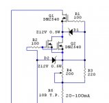
Just connect two identical CCS parts (the two DN2540) in parallel....if it is possible to get higher current? I need 140mA with 250V voltage for my lamps.
Just connect two identical CCS parts (the two DN2540) in parallel.
Will it work? Did you try?
Shure it'll work, tried and working. Not in the SSHV though. But I'm sure it'll work here too.Will it work? Did you try?
You can test it yourself if you like: just 4 DN2540 and 4 resistors are easily put on any breadboard and powered by a battery or any PS in the range of 20-30V.
Congratulations. 400V out and not 300V out you probably mean?
At the moment i am only outputting 300v, but i am still in the mockup stage so that may change. If anything i think my B+ may come down to 400v after all.
No, I'm afraid you'll have to duplicate the whole cascade CCS, like in the attachment. The only possible simplification is to make common the R3, R4, but if you'd like to use a trimpot I'd better to stay with full circuit.Poty, thanks for the idea. So I have put together 2 pieces of DN2540 as shown?
Attachments
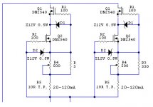
No, I'm afraid you'll have to duplicate the whole cascade CCS, like in the attachment. The only possible simplification is to make common the R3, R4, but if you'd like to use a trimpot I'd better to stay with full circuit.
Thanks, will try it within few days.
Salas,
I rebuilt a blown supply and have a problem. I feed it 240v DC with a target of 180v DC. My target current is 50ma. I can adjust the current fine with R4. However I cannot get above 140v DC using R11, with the current at 50ma. I can get higher DC voltage if I adjust R4 to get 60ma. The output voltage does change with R4 adjustment. I did have to replace the LED. I suspect that the replacement is the issue. I think it is a 20ma LED. Would the wrong LED cause this problem.
John
You probably use too heavy a test load. Else, something is wrong with the semis in the shunt voltage part. Read that older discussion also http://www.diyaudio.com/forums/powe...tic-mosfet-hv-shunt-regs-450.html#post4113497
Hi. Im thinking of putting a protection feature to one of those boards. I want it to serve 8-9mA, put an overhead of 20 to 28-29ish but shut down at say 12ish. Can I increase R5 and put some low treshold fet to drive a relay or how would you have done?
The ccs in the reg will be a steady thing for its limit so better put an in line small value measuring resistor in the client application itself, make an op amp comparator measuring the drop across it against a ref voltage so if passed it saturates and opens a relay
The ccs in the reg will be a steady thing for its limit so better put an in line small value measuring resistor in the client application itself, make an op amp comparator measuring the drop across it against a ref voltage so if passed it saturates and opens a relay
Cathode resistor on upper cathode follower maybe. Can even split it in two and use drop on the lower not risking parasitics or so direct on the cathode.
Salas,
In message 4493 you say that Q4 should measure in the kilo Ohm range. When I test it from E to B, it is always in the mega ohm range. Am I testing it correctly? To my untrained eye, looking at the schematic the mega ohm range should be correct.
I do get the expected reading for Q5.
I need around 80 to 90ma, I believe that this is within the operating range for the PS.
I am having trouble getting the IRF840. Does the Gate Charge (Vgs) matter?
Thanks John
- Home
- Amplifiers
- Power Supplies
- Simplistic mosFET HV Shunt Regs