Why if the only change is with or without the RC filter?
The RC filter, if placed after the SSHV2, changes the way and the degree the SSHV2 regulates.
From the technical viewpoint, a filter after the regulator decreases its' performance.
Yet, if it sounds better to you - go for it.
However your conclusion that it sounds better is due to HF interference is not proved, it's a blind guess, not necessarily a correct one.
Merlin, use whatever you think makes your sound better but always compare with minimum additions possible first. Just always use series resistance when you add shunt capacitors to the rail after this particular reg. It does not like them straight up.
I think that you think that you got the answer.Thanks Salas, finally I got the answer to my question.
As you pointed out it was different PSU and different circuit. It doesn not answer the question asked:merlin el mago said:... in other PSU for other load I compared with or without filter and my ears prefered with filter.
You wonder:stajo said:How did you conclude that you have a HF ... problem?
Power supply (having also output voltage and current capabilities) has 2 main - say - quality parameters: amount of input pulses filtering (PSRR) and output impedance defining the load characteristics. First parameter defines hom much garbage you will have on your power supply rails, second - hom much voltage fluctuations you will have due to consuming current change for your circuit.merlin el mago said:Why if the only change is with or without the RC filter?
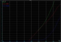
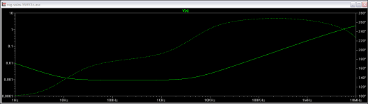
Lets see what we have in the case of using SSHV (see attachments). Really our concern is up to 1MHz, because all higher frequencies should be treated much differently.
Filtering is great without any additional RC (at 1M it's more than 100dB! - 1V input pulses will ideally output in 10microVolts). Putting the RC after the SSHV "improves something which is already great" (25dB more), but as you can see - even better results (still useless improvement) you can achieve with the filter just before SSHV.
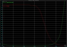
Output impedance graph shows clear problem for the case "filter after the SSHV". Audio signal top frequency (that is what would be in the current changes) is 20kHz, at this frequency we have milliOhms in cases of "no-RC" or "RC-before-SSHV" and around 1 Ohm in case of "RC-after-SSHV". It means that changing the current to 10mA will lead to changing the voltage to 10mV ("RC-after-SSHV") and around 0.05mV without the RC.
So, adding the RC after the SSHV does not improves anything and adds some potential problems to the circuit.
By the way - why do you chose the 53 kHz?
Attachments
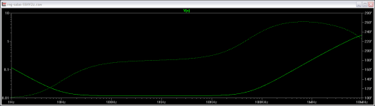
As far as I simulated the SSHV I tried to add the second CCS in place of cascode's load. I can't see any problem with Zo. Overhead in parts - one JFET.
Maybe you added a perfect CCS? When I was making it I found the resistive load smoother sounding than a 2SK117GR degenerated for same ~2mA DC bias.
When I run the LTSPICE I saw that the rate of Zo climb around 10kHz got steeper, no surprise. To have less overall Zo but smooth and extended it takes a compound feedback pair in the output. Such a decision would render the reg much more reactive load intolerant in my experience. Given the field of application, i.e. tube builds with significant distances from sense nodes to consumption nodes I opted to stay with simple drive arrangement and good enough Zo but smooth and tolerant phase. People came to apply it even on small SE amps (see recent Bartola report) #26 preamps and phones amps with large inductive anode loads. Quite a range of successful applications. So with the benefit of hindsight I consider that original decision adequate.
Attachments
Sorry, to clear the mess///
This is to Merlin:
I don't know exactly if it is the problem of translation or the values (I mean the values of the serial resistance for capacitors) put here deliberately... In the real life you'll have different results (for example - try to change the serial resistance to 2 Ohm in your PSUD simulation - you'll be greatly surprised)
Second - have you read the text? The 1Ohm-3uF were putted here to control channels separation, not pulse reduction.
Third - you already have the active circuit (SSHV) doing much better job for you in filtering and speed - why to lower its great capabilities for nothing added?
Forth - to achieve great channel separation you can made 2 SSHVs and don't think more about it.
To Salas:
I did the simulation with the same CCS as in the base circuit of the cascode, but tuned for 3.6mA. I use other program, not LTSpice and maybe that is the answer to differences (different models and so on).
Last edited:
To Salas:
I did the simulation with the same CCS as in the base circuit of the cascode, but tuned for 3.6mA. I use other program, not LTSpice and maybe that is the answer to differences (different models and so on).
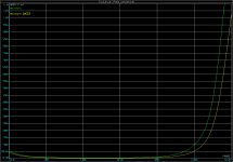
Something's missing because when applying a CCS on the error amp, especially when higher in mA than with the resistive load you MUST get more OLG. That should show several fold drop in Zo at least over a significant portion of your curves. But they look running at almost same level in most of your posted chart (last one with yellow and green lines).
Merlin, use whatever you think makes your sound better but always compare with minimum additions possible first. Just always use series resistance when you add shunt capacitors to the rail after this particular reg. It does not like them straight up.
Salas, finally I left the SSHV2 without the RC filter.
Hello Salas
About the HF oscilation
I measure round 80Mhz on output SSHV2, can this be the switching from the IRF?
It's round 1Vtt
I use it in a phono stage and it's comes on the output of my amp (output from anode tube)
Can this be a problem?
About the HF oscilation
I measure round 80Mhz on output SSHV2, can this be the switching from the IRF?
It's round 1Vtt
I use it in a phono stage and it's comes on the output of my amp (output from anode tube)
Can this be a problem?
Press the bandwidth limit button on the scope. There is no way it can oscillate at 80MHz. Its too high a frequency for it.
Hi Salas, I bought the parts for your regulator a long time ago but I never build it, now I'm about to but it's the old version and I have the parts for the 250 volts regulator. I have the MPSA92 not the 2n6520. My preamp current is 10mA, I plan to set the CSS for 20mA. 350 volts in, 300 volts out. Anyway my question is this: do you think it would survive? If you say NO NO, would be a good idea to use a 2K resistor in my CRC filter to go down to 300V?
Can you point me to the exact circuit you have bought the parts for, first? Is it the one in post#2?
That's right, post #2. My transformer is huge so another idea is to set the CCS for high current and use a dropping resistor of lower value. I'm talking about the resistor in the CRC filter. CCS for 50 mA and 1K resistor instead of 2K.
I don't care if the B+ out of the regulator is 250V instead of 300V, the problem is that after the tube rectifier and CRC filter my B+ is 355V and I'm afraid it might be too much for the circuit in post #2. But I really don't know that's why I'm asking.
- Home
- Amplifiers
- Power Supplies
- Simplistic mosFET HV Shunt Regs