No I didn't measured the parts burned, Q1 DN2450 was destroyed.
I discovered D3 in the schematic & D1 in the GB pcb was burned, I desoldered one leg & now can reach 60mA of current but Vout fixted 26V, I follow looking for where is the issue so I will measure, irf840, 117 & 1381.
I discovered D3 in the schematic & D1 in the GB pcb was burned, I desoldered one leg & now can reach 60mA of current but Vout fixted 26V, I follow looking for where is the issue so I will measure, irf840, 117 & 1381.
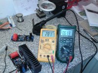
Actual readings
IRF840 3,67
SK117 0,203
KSA1381 0,203 (Q5 pcb GB)
KSA1381 0,590 (Q4 pcb GB)
Heatsink Q1 DN2450 very hot.
IRF840 3,67
SK117 0,203
KSA1381 0,203 (Q5 pcb GB)
KSA1381 0,590 (Q4 pcb GB)
Heatsink Q1 DN2450 very hot.
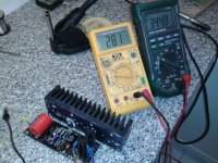
Out of curiosity, and to make sure that there is no problem with the board or the GB kits, I quickly solder and tested one more SSHV2. It took an hour to build and test it.
As you can see all went fine and there is absolutely no problem.
Felipe, I think that you are doing something wrong on your build, maybe some photos would help.
As you can see all went fine and there is absolutely no problem.
Felipe, I think that you are doing something wrong on your build, maybe some photos would help.
Attachments
Can be C1 0,33uF damaged?
George, Salas, was changed C1 for a new 0,33uF 400V and now the regulator isgoing on OK 240Vout 60mA🙂
Thank you very much for your support.
Felipe
What a bad luck! 1/1000 odds to chance on a bad passive plastic component! Let us know if you find it any better in use. Wishing no more weird stuff comes up.
Let us know if you find it any better in use. Wishing no more weird stuff comes up. What types of caps did you use? Was it new?
Did you measure the damaged cap?
That could be helpful feedback for future builds from other members.
Did you measure the damaged cap?
That could be helpful feedback for future builds from other members.
Last edited:
I think he had an Infinicap on that pic. Has a funny end termination technique. Could it have been intermittent if bent a few times in the past?
Oh, oh, imagine if it was shorting to the extra pads under it...
http://www.diyaudio.com/forums/parts/28250-trt-infinicap-warning.html
http://www.diyaudio.com/forums/parts/28250-trt-infinicap-warning.html
What types of caps did you use? Was it new?
Did you measure the damaged cap?
That could be helpful feedback for future builds from other members.
Damaged cap measures 9nF😡
I think he had an Infinicap on that pic. Has a funny end termination technique. Could it have been intermittent if bent a few times in the past?
Oh, oh, imagine if it was shorting to the extra pads under it...
http://www.diyaudio.com/forums/parts/28250-trt-infinicap-warning.html
Interesting to know & in the future avoid problems.
George I don't have words to describe the very big upgrade using the SSHV2, I never suspected that tubes can reach same or very near level of information like SS, now I understood (thanks to Salas) how much important is to have a very good shunt regulator, also thank crt to his layout & to Tea-Bag for the GB and all people like you & others testing the beta boards to be possible all of us enjoy your splendid work, thanks to everybody involved.
Good that you like it!
The comparison is with SSHV1, right?
When you listen more to it, a more detailed feedback will be welcome.
And always be careful with HV.
The comparison is with SSHV1, right?
When you listen more to it, a more detailed feedback will be welcome.
And always be careful with HV.
Yes compared vs SSHV1.
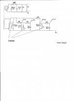
I have a little of hum, my psu is CLC 150uF+10H+150uF, original psu attached, it's possible that I need more capacitance to eliminate the hum?
N.B. proper grounding following the diyAudio.com Articles: Audio Component Grounding and Interconnection
http://www.diyaudio.com/forums/diyaudio-com-articles/163575-audio-component-grounding-interconnection.html
Help will welcome.
Attachments
Good report, ending well = all well. I don't think that any hum has to do with line ripple especially when with regulated B+. First of all 100Hz ripple would sound more like a 'bzzz', its harmonic noise with many midrange peaks, 50Hz sounds deeper like ''hUmmm''. Can be some small ground loop or field. Possibly. Even instability, but that normally sounds bad too and heats up much.
I increased 220uF the PSU but isn't fixed.
I grounded the MM RIAA chasis because Speakon is only 4 pole (2 for heaters + 2 B+) so I wired one cable between GND chassis PSU to GND chasis MM RIAA & the hum isn't fixed, I have the same level/amount of hum but the tone changed seems more low after seemed more high.
I grounded the MM RIAA chasis because Speakon is only 4 pole (2 for heaters + 2 B+) so I wired one cable between GND chassis PSU to GND chasis MM RIAA & the hum isn't fixed, I have the same level/amount of hum but the tone changed seems more low after seemed more high.
I increased 220uF the PSU but isn't fixed.
It isn't ripple. Keep on searching grounding, move the regulator to hear possible difference, post the phono photo & schema with points of PSU receive.
- Home
- Amplifiers
- Power Supplies
- Simplistic mosFET HV Shunt Regs