Hi Salas,
Sorry another question. If the Reg is built outboard,
should a cap be needed on the main board ?
Thank you again.
Sorry another question. If the Reg is built outboard,
should a cap be needed on the main board ?
Thank you again.
Put a good film cap on board with the circuit, say 10uF, very near to its consumption point after all cable. That will act as a local bypass. The reservoir capacitors before the PSU are the storage, and this energy passes through.
salas said:
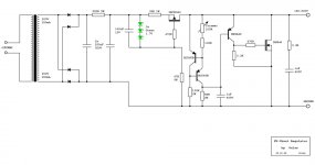
P.S. Is this the preamp you are talking about? If yes, the PSU examples that you see here are overkill for current, dissipation - heat sinking. So, I instruct you a tailor made power scaled schematic if I may. You can see it attached. A 230V 100mA transformer and 4X UF4007 arranged as a bridge rectifier feeding a 220uF/350V capacitor is all you need for Vin. Also 2X rudimentary 3W heat sinks like those they mount LM317T regulators on.
Euxaristw para poly for the advice Salas!! 😉
salas said:
So, I instruct you a tailor made power scaled schematic if I may. You can see it attached. A 230V 100mA transformer and 4X UF4007 arranged as...
Salas I am confusing myself. When you say I will need a 230V transformer, do you mean with 230V secondaries?

According to the personalised schematic you prepared for me 😀 don't I need a trafo with 320V output ???
Here in the UK we have 230V mains, therefore I will need a trafo with 230V input, 320V output right??
From a quick look in farnell I can't find any suitable trafo. Did you wind your own trafo ?
230V primary and 230V secondary, happens you need 1:1 ratio in this case.
Parakalw (you are welcome).😉
Parakalw (you are welcome).😉
salas said:230V primary and 230V secondary, happens you need 1:1 ratio in this case.
Parakalw (you are welcome).😉
I see.
I was confused because you specified 320V (in red circle) in the schematic attached, so I thought a trafo with 320V out was needed.
Kalo brady
Attachments
320V indeed but rectified DC, not AC. Its a regulator, needs DC. You will get over 300V DC when you rectify your 230V AC secondary.
Goodnight to you too, be careful with the high voltages, keep one hand in your back pocket when testing your new 12AX7 preamp and shunt PSU.
Goodnight to you too, be careful with the high voltages, keep one hand in your back pocket when testing your new 12AX7 preamp and shunt PSU.
thanks for the advice, much appreciated
I have one more question, last one hopefully
I can't find BC560B's here in the uk, only BC560A or BC560C
the difference is in the hFE value
A is 110-220, B is 200-450 and C is 420-800
does it make any difference if I go for the BC560C ?
I have one more question, last one hopefully
I can't find BC560B's here in the uk, only BC560A or BC560C
the difference is in the hFE value
A is 110-220, B is 200-450 and C is 420-800
does it make any difference if I go for the BC560C ?
It will pull a little more current for the C version, will make an even better current source for noise, it may give more V out voltage. Keep in hand 110R and 120R resistors for R5 along with the original 100R, so to practically use the one that will get you nearer to your target voltage. This voltage reference is based on transistors and a resistor and there will be thermal effects in the first 5 minutes until everything warms up and the voltage will stay stable a bit lower than at the power on moment. It's non the less much better than using a Zener. Plus it can be easily trimmed.
Hi Salas,
I am curious because I use a normal series regulator and despite it make his work very precise I have to admit that it sound bad.
I prefer unregulated, well filtered.
Note I understand near zero of electronic but my ear is very good;
I have heard rumors about the "shunt" type regulators that they are near transparent, invisible, do not affect the sound. Issues is they can't manage big current.
Seems to me you have solved the problem of current , right?
So my question is very basic: can you confirmate your circuit is good as a old, unregulated CLC ?
perdone my poor english!
Cheers,
Paolo
A CLC is just a basic passive SERIES filter. Those shunt IRF Mosfets can dissipate 120-150W, you can run as much current as you like up to that if you use big heat sinks. That means 600mA at 200V as an example WITHOUT delivery to load. The more you deliver, the less goes to the heat sink of the shunt Mosfet. If you deliver 300mA, you burn 60W. And then there are stronger Mosfets. Practically you can design for Amperes if you like it and can tolerate the scale of sinks and power expenditure. Unrealistic? Yes the current limit is no problem for realistic valve circuits as it turns out.
Second thing you asked is about the sound. There is no way that a CLC can even touch such a regulator subjectively. Been there done that. Especially in low level circuits like a phono stage, the basic passives are useless anyway. You can cascade 5 RC or 3 LC.
You end up using so much SERIES resistance. Want to cut lower than RC? Must use some big, very well built and very expensive chokes in the 20H area, just to have some silence. And then what? Every time you have a dynamic demand, that series resistance modulates along because it is in the AC loop. It is still too much. Current? Ask for some substantial current and the chokes will saturate. OK build it double the size. Pay in the thousands of Euro in the end, if there is some top quality involved.
The shunts have mOhm output resistance, negligible ripple noise or hiss. Don't trust me, go build one and listen. Its much cheaper than a decent 2H choke. Then post your experience.
Oh thanks Salas ,
I have always thinked that series resistance was a bad thing, now you confirmate my suspect.
I understand your point about huge cost for a well dimensioned CLC,
it is true 😀
Neverless, BEFORE your special shunt regulator, I have tried a bit of series regulators and I prefer unregulated
Now your circuit seems to me a unique opportunity to find a "solution".
For my very limited skills The regulator is in parallel with the load so his bad sonical influence could be very reduced.......
I have to talk with my old friend who make this toys for my fun and see if he is disponible in short times...or long 😀
Thanks again for your precious expertise, I appreciate a lot 🙂
Cheers,
Paolo
Good luck Paolo with the shunt. Its easy to make. For any problem just ask. For series regulators you don't like there is a reason. Those are normally high feedback complex ICs or there is one in there with some help around it. So you actually wrap a tube no feedback(?) design in them. Bad marriage. So your passive sounds less forceful but natural at least in comparison. Those things are in series with AC. Anything you use, has a sound.
Salas,
you are so kind!
Your explanation is exactly the same I have learned from big italian master, Bartolomeo Aloia's articles and publications.
So you have to be a real guru, man ! 😎
Thanks again 🙂
Cheers,
Paolo
you are so kind!
Your explanation is exactly the same I have learned from big italian master, Bartolomeo Aloia's articles and publications.
So you have to be a real guru, man ! 😎
Thanks again 🙂
Cheers,
Paolo
Then I share.
Sharing he does indeed! Very appreciated 🙂
I took the freedom to redraw Salas' schematic for better readibility, and he encouraged me to post it here.
This will be for a spud headphone amp (very much like the ones
you have lately seen here on diyaudio 😉 ) the project so far just being on paper of course...
Attachments
- Home
- Amplifiers
- Power Supplies
- Simplistic mosFET HV Shunt Regs