I revise it.Are you sure, that SSHV2 shunt regulator is the best option?
The SSHV2 output voltage ramp up enough slow to hide this ringing (then the shunt modifying the Q of L ringing).
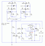
Simulating (not tested!):


Great! Please comfirm changes are:
*D1 D2, remove.
*R1 R2, from 100 to 8 Ohm
*R5, remove
*R9 R10, from 68K to 26K
*R12, from 470 to 1K
*D1 D2, remove.
*R1 R2, from 100 to 8 Ohm
*R5, remove
*R9 R10, from 68K to 26K
*R12, from 470 to 1K
The most important:
Practically must to duplicate built in CCS to achieve load current + 10-15% shunt current capability!
Practically must to duplicate built in CCS to achieve load current + 10-15% shunt current capability!
Paralel CCS, can achieve twice the current, nice,.
But I am worried to lose the original cascode, I see it as an enhancement in terms of sound quality.
Also is need cut traces below PCB and wiring PTP.
There is no another way less obtrusive?
But I am worried to lose the original cascode, I see it as an enhancement in terms of sound quality.
Also is need cut traces below PCB and wiring PTP.
There is no another way less obtrusive?
Hi, I read specs on IXYS series, and found idss IXTP02N50D at 200mA, a bit higher than DN2540 (150mA.)
Could be enough, and IXYS series may provide better sound, even.
Any further changes on R4 /200R, or other components around the cascode mosfets to reach 175mA.?
Thanks,
Jordi
Could be enough, and IXYS series may provide better sound, even.
Any further changes on R4 /200R, or other components around the cascode mosfets to reach 175mA.?
Thanks,
Jordi
Last edited:
Can't say for sure that an alternative part number Q1 Q2 is going to be plug and play with same resistors. Including gate stoppers stabilizing value. Also R5 could be a choke point against achieving Id near Idss. Better a one Ohm.
What I suggest to you when you will get the IXYS is to try the CCS section on a breadboard with low voltage first.
Say 15-25V. So to establish resistors tweaks if necessary. Useful to even find out the R4 value for your samples and setting. To can replace with a normal resistor and not keep the trimmer with its wiper contact. For better future reliability at the high enough mA target you aim at.
Not essentially different an analysis to the troubleshooting method of #4,479.
Reg is perfectly Ok. by using half load I need. One cemented stick only 1K/15W. I confirmed (as in pic atch) it is within the SSHV2 specifications, is reached wanted 77V. by using 85mA. (T.P. is 1R)
But my speaker filed coil load is twice stronger, same 77V but at 500 ohm.
When placed the second stck, in paralel of course= 500R/30W, then the Reg can't reach over around 100mA. and the output tension collapse around half value... 40 Volts or so.
In the meantime I received IXYS, lets play around gate stoppers on those cheap DN2540, I have spares, so no fear blowing up some. How to increase bias, reducing gate stopper value, from existing 100R ?
Do I must decrease value on both on cascode at once?
Attachments

Last edited:
Nice up to now. Of course it limits when load>CCS mA. Enters protect mode.
Gate stoppers value you will increase only in case of AC oscillation with IXYS.
R4 you predominantly experiment with for mA. Replace Q1 with IXYS at first.
If IXYS will give higher Vgs than before over Q2 DN2540, its max may improve.
If not enough, make Q2 to IXYS as well. To see how far this IXYS cascode will go.
I placed IXYS on Q1 ( IXTH6N50D2) and I am afraid, could be this so much powerful mosfet for this application?
I have no readings at all. Absolute zero everywhere!
Desoldered and soldered different samples, also placed DN2540 in between just to confirm the pcb is healty. So no clue how to proceed, other than order other IXYS less powerful.
I have no readings at all. Absolute zero everywhere!
Desoldered and soldered different samples, also placed DN2540 in between just to confirm the pcb is healty. So no clue how to proceed, other than order other IXYS less powerful.
Try model those IXYS ccs on a breadboard using a low voltage supply to better see how they bias etc.
I doubt he doesTry model those IXYS ccs on a breadboard using a low voltage supply to better see how they bias etc.
R4 full clockwise to zero and no success. Not any mA. reading.
I have breadboard, but I am afraid lacking knoleadge to do so.
I have breadboard, but I am afraid lacking knoleadge to do so.
- Home
- Amplifiers
- Power Supplies
- Simplistic mosFET HV Shunt Regs