It's working very well! You were right, with a load voltage is easy to adjust and stays constant.
My transformer gives me 37V unloaded and I adjusted the capacitance multiplier output to 35V. When a load is connected the transformer will give less voltage, it's rated 25Vac when full loaded at 6A per secundary. So, will the cap voltage tracks the transf voltage, that is, when the input voltage decresses one volt will the output also decrease 1V (so the 2V voltage drop remains constant) or it will stay at 35V even if the input is 36 or 35?
What fuse rating should I use?
thanks!
Last edited:
Thanks for the feedback.
When the transformer voltage sags under high load the output will follow, though relatively slowly. That's the beauty of the CM supply, it gives most of the benefits of regulation without being a regulator.
For a pair of VSSA or similar, 6-8A for the fuses will be fine.
When the transformer voltage sags under high load the output will follow, though relatively slowly. That's the beauty of the CM supply, it gives most of the benefits of regulation without being a regulator.
For a pair of VSSA or similar, 6-8A for the fuses will be fine.
Ok 🙂 Have My PS board.. completed?
(under ordered a few wee caps so had to substitute from on hand, same values tho)
Couple of small questions:
What size Fuses ? (240va 28 v Torroid) ooops just read the above: 6-8 amps then ??
Is there a diagram for connections to the myriad wire attachment points?
Not wiilling to simply guess , hope and risk...at this point 😱
Thanks
Attachments
Last edited:
Hi Bare,
The connections should be pretty straightforward. Hardest part will be proper phasing of a dual secondary transformer. As I recall you got an Antek that has dual secondaries and should also have colour coded leads and a connection diagram, so it should be straight forward compared to some.
The end with the pass MOSFETs has three sets of euroblock connectors (spades could be used there if desired). Two sets are labeled as +V GND -V, and are meant to power the amplifiers. The three GND connections in the middle are just for added flexibility in how you return things to the PSU, some have very specific ideas on that.
The input side has two euroblocks (or again spades could be used) labeled +V GND, or -V GND. They can be used to feed DC out to something else that doesn't need to pass through the capacitance multiplier, or alternatively, they can be used to feed the circuit from off-board dual rectifiers. Once again some added flexibility.
The main AC inputs are set-up to accommodate either dual secondaries or a centre-tapped secondary.
For a centre-tapped secondary the connections are AC1A-CT-AC2B.
For dual secondary the connections are AC1A-AC1B and AC2A-AC2B, with the 'phase dots' (same colour leads) located at AC1A and AC2A. The CT connection can be again used as an auxillary ground point.
For your specific transformer brand, if I recall you bought one from Antek:
AC1A - Green lead from either secondary
AC1B - Blue from the same secondary as AC1A
AC2A - Green lead from the other secondary
AC2B - Blue from the same secondary as AC2A
Hi Bare,
Yes the primaries are connected in parallel for our region in the world, ~115VAC mains @ 60Hz. Red to red and black to black.
The purple shield wire should be connected to the main chassis ground, right where you should have a bonded mains ground wire to the chassis. I usually use a longish brass bolt and put the mains ground connection at the bottom with appropriate washers and a nut. Anything else that should go to the 'protected earth' gets connected on top of that. Quick diagram attached.
Attachments
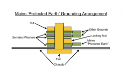
Is the purple wire the interwinding screen?
The screen's purpose is to conduct interference to "Earth".
This is done by inserting a low impedance connection from the internal screen to the Chassis and then capacitive coupling from the Chassis to "Earth" (that big round ball that we all sit on while listening to out music).
For a low impedance connection, the wire link should be short. If the wire link is long then it will have higher impedance due to inductance of the longer wire.
Take the screen connection direct to Chassis at the point that the screen wire exists the transformer insulation.
If one does not do this, then the HF and VHF and UHF components of the interference will see a high impedance connection to Earth.
I failed to mention that I have extra boards if anyone is interested. They are 2oz copper on FR4, double sided, plated holes with solder mask and silk screen. It might be nice to get some feedback or input from builders about what would improve it in the future. It will accommodate a fair range of devices and works well. Feel free to PM me if you want to give this PSU a try.
I am interested in 2 boards if you have them.
Rick G.
Hi Rick,
I know I have one on hand, and I will have to check to see if I started to stuff a second one for myself or not (I don't think I started it). I'll PM you with firm availability later.
I know I have one on hand, and I will have to check to see if I started to stuff a second one for myself or not (I don't think I started it). I'll PM you with firm availability later.
Jason,
The board arrived this morning all snug & in Great shape. Nice Board. Also i appreciate the BOM being included as well. 🙂
Thanks,
Rick
The board arrived this morning all snug & in Great shape. Nice Board. Also i appreciate the BOM being included as well. 🙂
Thanks,
Rick
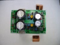
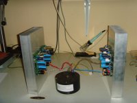
Gentlemen, I have equipped the Nelson Pass ACA#1 - PCBs of my current 4-channel ACA - build, being used for the high- and middle tones of an active speaker-project,
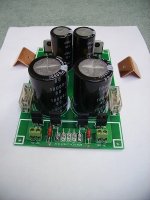
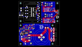
with onboard Jason's CAP-multiplier (image1).
I have adjusted the ACAs (using a 4x20VAC/300VA custom wound torroid - image2)) to an operating voltage of 24.5VDC and an ACA "bias voltage" of 12VDC.
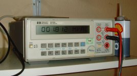
I am measuring an incredibly low ripple of <2mVAC (image 3) on the output voltage.
In my eyes (ears): Jason's CAP-multiplier (which is even adjustable within a small range) is a real gem, and you will get hooked on the ACA's sound.
Why should you ever go for any other PSU, giving you a "small" (about 1.4A) current?
Best regards - Rudi_Ratlos
with onboard Jason's CAP-multiplier (image1).
I have adjusted the ACAs (using a 4x20VAC/300VA custom wound torroid - image2)) to an operating voltage of 24.5VDC and an ACA "bias voltage" of 12VDC.
I am measuring an incredibly low ripple of <2mVAC (image 3) on the output voltage.
In my eyes (ears): Jason's CAP-multiplier (which is even adjustable within a small range) is a real gem, and you will get hooked on the ACA's sound.
Why should you ever go for any other PSU, giving you a "small" (about 1.4A) current?
Best regards - Rudi_Ratlos
Attachments

Glad you like it and I appreciate your kind words.
Of course, the design is just my spin on the work of MrEvil. It looks like the concept, as re-worked by Rudi, suits the ACA well.
Congratulations to you Rudi and I hope the others who have benefited from your efforts enjoy it too.
Of course, the design is just my spin on the work of MrEvil. It looks like the concept, as re-worked by Rudi, suits the ACA well.
Congratulations to you Rudi and I hope the others who have benefited from your efforts enjoy it too.
Rudi
How do you think the CAP-multiplier would work with the FC-100 amp - somthing worth trying?
Jason, do you have any boards left for sale?
Thanks
How do you think the CAP-multiplier would work with the FC-100 amp - somthing worth trying?
Jason, do you have any boards left for sale?
Thanks
Gentlemen, I have equipped the Nelson Pass ACA#1 - PCBs of my current 4-channel ACA - build, being used for the high- and middle tones of an active speaker-project,
with onboard Jason's CAP-multiplier (image1).
I have adjusted the ACAs (using a 4x20VAC/300VA custom wound torroid - image2)) to an operating voltage of 24.5VDC and an ACA "bias voltage" of 12VDC.
I am measuring an incredibly low ripple of <2mVAC (image 3) on the output voltage.
In my eyes (ears): Jason's CAP-multiplier (which is even adjustable within a small range) is a real gem, and you will get hooked on the ACA's sound.
Why should you ever go for any other PSU, giving you a "small" (about 1.4A) current?
Best regards - Rudi_Ratlos
Rudi
How do you think the CAP-multiplier would work with the FC-100 amp - somthing worth trying?
Jason, do you have any boards left for sale?
Thanks
Hi marcus1,
Sorry to say I do not have any boards left. The files have been downloaded a fair number of times; maybe someone else had some made?
I think the supply can be used with any amplifier that falls into the mid-range power level that might benefit from a quiet supply. Always worth a shot.
Jason, Marcus1: Roender's FC-100 is a very powerful amplifier with 3 TO-264 output transistors (NJL0281 / NJL0302) on each power-rail.
Moreover: the FC-100 design distinguishes very precisely between frontend- and backend power-supply. For example: Roender developped a very precise shunt regulator to drive the frontend of the FC-100.
In contrast the backend power-supply is simple: rectifier diodes and reservoir caps.
I myself would not use Jason's cap-multiplier to power the FC-100.
A lot of other "smaller" amplifiers (like the standard SYMASYM or the ClassA ACA#1 f.e.) would/do benefit from Jason's CAP-multiplier though.
I have done a layout for Jason's PSU and ordered a couple of PCBs (together with a dual LT1763-based PSU on the same PCB - I will cut the PCB).
The PCB's sizes are:85x50mm (Jason's PSU) and 90x50mm (the LT1763 PSU).
The PCBs will arrive in 2-3 weeks.
I can offer you one (more?) of these PCBs.
Best regards - Rudi_Ratlos
Attachments
Last edited:
Rudi
How do you think the CAP-multiplier would work with the FC-100 amp - somthing worth trying?
Jason, do you have any boards left for sale?
Thanks
You could use a cap multiplier to provide a cleaner supply to the front end of the Roender amplifier.Jason, Marcus1: Roender's FC-100 is a very powerful amplifier with 3 TO-264 output transistors (NJL0281 / NJL0302) on each power-rail.
Moreover: the FC-100 design distinguishes very precisely between frontend- and backend power-supply. For example: Roender developped a very precise shunt regulator to drive the frontend of the FC-100.
In contrast the backend power-supply is simple: rectifier diodes and reservoir caps.
I myself would not use Jason's cap-multiplier to power the FC-100.
A lot of other "smaller" amplifiers (like the standard SYMASYM or the ClassA ACA#1 f.e.) would/do benefit from Jason's CAP-multiplier though.
I have done a layout for Jason's PSU and ordered a couple of PCBs (together with a dual LT1763-based PSU on the same PCB - I will cut the PCB).
The PCB's sizes are:85x50mm (Jason's PSU) and 90x50mm (the LT1763 PSU).
The PCBs will arrive in 2-3 weeks.
I can offer you one (more?) of these PCBs.
Best regards - Rudi_Ratlos
I would not use any form of multiplier/regulator to supply the "power" end of the Roender. As from Rudi, a simple rectifier/smoother is sufficient.
Hi donovas,
The TIP142 / TIP147 have a lower effective 'threshold' than the MOSFETs, so the resistor values are somewhat dependant on two things, the bulk supply voltage and the output device threshold value.
Referring to the last schematic on the first page of this thread, assuming ten posts per page, R17 and R8 set the tail current and should be calculated to pass about 4-5mA of current. They will see about half of the bulk supply, so a quick calculation using Ohm's Law and select the standard resistance closest to the calculated value that puts the current in the desired range.
Next we need to calculate the appropriate values for R22 and R23 to accommodate the output device threshold voltages. We want to have about half of the tail current through each of these resistors. Assuming a TIP142 / TIP147 are turning on at Vbe of 1.3V and we want about 2-2.5mA through R22 and R23, we would want values of about 680Ω in those places.
You may have to adjust your resistor values experimentally, you have chosen to work with an earlier schematic. Later versions used a simple CCS to reduce some dependance on supply voltage in setting the operating conditions.
i just realized i have using tip142/147 without pinout change from your original pcb from the first page, meant for mosfets. and the circuit has been working fine, sounds great. what's been happening here? 😕
the voltage can be adjusted, the darlingtons are lukewarm to the touch. tip142 in the positive rail. i just dropped it in the mosfet slot without bending legs or even thinking about it...
Last edited by a moderator:
There is no issue with the Darlington BJTs, same pinout as vertical MOSFETs. As previously discussed, just scaling the collector resistors to suit the effective threshold voltage for the chosen device.
In short, it is working as intended.
In short, it is working as intended.
ah good to know, thank you.
i etched the original jlh cap multiplier which had different connections for tip142/147, which's what got me wondering.
i etched the original jlh cap multiplier which had different connections for tip142/147, which's what got me wondering.
- Home
- Amplifiers
- Power Supplies
- Simplified MrEvil / PMI Capacitance Multiplier