either fit a speaker delay at start up with instant off on loss of mains power
or
leave the headphones out during switch on and ensure any capacitor/s have time to charge up before plugging the headphones in.
or
leave the headphones out during switch on and ensure any capacitor/s have time to charge up before plugging the headphones in.
Have you measured any of your components to verify the two rails have the same (withing reason) values? Does it exhibit this when unloaded or with equal resistive loads?
If there are significant differences in component values, especially relating to the rail filtering parts then one rail might rise at a different rate than the opposing rail.
If the load draws more heavily from one rail during startup then the PSU output may rise at a lower rate on the more heavily loaded rail.
My experience has been very symmetrical behavior between the rails. I have not had any issue with the PSU causing a turn-on thump.
all the resistors are 1% tolerance. the transformers have .5v ac difference between the halves, which is amplified to 1v dc difference at the output. i put a trimmer on the pcb to even out the voltages but the thump is still there...
I'd be very surprised to find a production transformer produce a 0.5 volt ac difference on two secondary windings, particularly if it's a torroid - that voltage difference might be caused by a 'dud' diode, for example.
If you do indeed have a difference in the ac secondary voltages, and they have a common connection in the centre (centre tapped), you might consider adding an extra series diode, for example, to absorb the 0.5 volt ac, or insert a resistor, etc or just replace the transformer
One thing that may produce a 'turn on/off thump' is possibly where you connect the 0 volt point on the supply - see if you have connected the centre 0 volt on the output of the C-Multiplier to the amplifier, speaker (headphs), etc including the one to the chassis earth - connecting it otherwise can produce all sorts of problems, particularly with the F5 headamp
If all this is okay, just do as Andrew suggested and attach a speaker protection cct on the output of the headamp- it'll delay the headph connection on startup and quickly disconnect it when turnoff - most of them operate with a dc voltage over 1 volt that isn't too kind to the headphones, but it will stop that 'thump' okay.
if you want to use a 'proper' headphone protection cct, there's a cct and pcb available on the AMB website (Epsilon 12 project) and a Cavalli Audio variation on their SOHA II project pages
And a true cap multiplier (open loop follower) without NFB will not have these problems.
Patrick
Patrick
im also trying to get this to work with irf9610. the current draw is 500ma. the cap multiplier only outputs 4v or so with 19v input voltage. the circuit works fine with tip147.
hi jason, i have another question- in the Q1 and Q2 position, is lower cob more desirable than lower noise, lower resistance? i'm swapping transistors around in that position, bc550 among others, and can't decide which sounds 'better'.
I like the BC550 / BC560 devices and the KSC1845 / KSA992 as well. Mind the pin-outs when swapping devices.
I'm not sure I believe the PSU should have much influence on the sound of an amplifier, that is unless the amplifier has near zero PSSR or the PSU is colossally bad.
I'm not sure I believe the PSU should have much influence on the sound of an amplifier, that is unless the amplifier has near zero PSSR or the PSU is colossally bad.
I have an idea that if you replace BC550C with IRF610 and replace BC560C with IRF9610, this will be the best power because the gate of MOSFET will not consume the current. Who can redesign it?
I had ordered to have a couple for myself but all my spares are now gone. I had been approached by a couple other forum users this summer who wanted to do a GB. I said I had no issue with that but don't know if they ever did a GB or not.
I needed for stereo +/- voltage.
The reason I ask because I know someone ordered that type.
I have to ask him where did he get them.
Someone offered me the separate type of PC boards.
Thanks
The reason I ask because I know someone ordered that type.
I have to ask him where did he get them.
Someone offered me the separate type of PC boards.
Thanks
Hi JasonKeutemann,
I am using this circuit now and it seems that it takes a 3.7v drop in order to sustain 3.7amp draw with low ripple and I have 22mF bulk capacitance.
The setting was confirmed with oscilloscope - before this I set it at 2.5v drop thinking that was sufficient but about 240mV of sawtooth was leaking through.
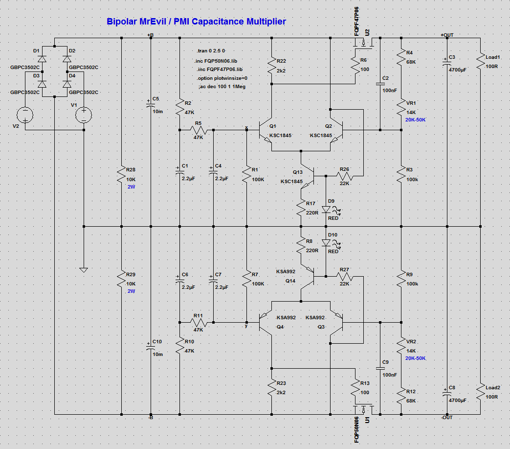
The more I look at the schematic, the more it looks like a pass through voltage regulator and not a capacitance multiplier. The usual dropout of a 78xx regulator is about 3.5v if IRC.
Which cap is being “multiplied” here? The 2.2uF C1? Usually the cap being multiplied is circa 220uF.
Thanks,
X
I am using this circuit now and it seems that it takes a 3.7v drop in order to sustain 3.7amp draw with low ripple and I have 22mF bulk capacitance.
The setting was confirmed with oscilloscope - before this I set it at 2.5v drop thinking that was sufficient but about 240mV of sawtooth was leaking through.
The more I look at the schematic, the more it looks like a pass through voltage regulator and not a capacitance multiplier. The usual dropout of a 78xx regulator is about 3.5v if IRC.
Which cap is being “multiplied” here? The 2.2uF C1? Usually the cap being multiplied is circa 220uF.
Thanks,
X
The more I look at the schematic, the more it looks like a pass through
voltage regulator and not a capacitance multiplier.
There doesn't seem to be a reference voltage, just the RC filtered input voltage,
so it isn't a voltage regulator. The R1 would have to be a Zener for the circuit to regulate DC.
Last edited:
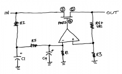
The general rule is: Diffamp_IN_+ == Diffamp_IN_-
[R1/(R1+R2+R5)] * Vin
is (by negative feedback) made equal to
[R3/(R3+VR1+R4)] * Vout
Notice that a 10% increase of Vin, produces a 10% increase of Vout.
It's not a "Voltage Regulator" because Vout is not independent of Vin.
Notice that it is a 2 stage amplifier and both stages have considerable amounts of voltage gain, but there is no explicit frequency compensation circuitry to guarantee stability. Minus fifteen points to Slytherin.
I know it doesn’t regulate to an absolute voltage - so maybe a ripple reducer - but I don’t see the cap that is being multiplied unless it is the tiny 2.2uF cap C1.
- Home
- Amplifiers
- Power Supplies
- Simplified MrEvil / PMI Capacitance Multiplier