Gotcha, thanks! but to my understanding that peaking midband is a problem with TPC, TMC doesn't have that problem.
Yes it does, just include both loops (global and compensation) in a simulation. It was long time ago shown that TMC is mathematically equivalent with TPC plus a lead compensation, there's nothing that would make TMC better than TPC, other then some eye candy illusion. Everything else being equal, both can deliver the same amount of loop gain.
Gotcha, thanks! but to my understanding that peaking midband is a problem with TPC, TMC doesn't have that problem.
I'd like to clarify even more.
Since impulse response are mathematically tightly coupled with frequency response we can talk about feedback gain shaping for nearly perfect aperiodic step response.
And to push this even further, for any compensation order (say 1 for Miller, or 2 for TMC or TPC, or 3 for Cherry NDFL), and given an amplifier open loop unity gain frequency, the maximum amount of available loop gain depends only on the compensation order. This is to say that extra loop gain can be obtained either by increasing the compensation order, or by increasing the open loop unity gain frequency. Alternatively, any push to get more loop gain by increasing the unity loop gain frequency comes with a stability margin penalty. Otherwise said, you can't have the cake and eat it too.
One would note that no assumptions are made above regarding the open loop amplifier topology. This is to say that CFAs are following the same set of constraints, and from Bode's "Maximum Feedback" perspective have no advantage over any other circuit topology. See https://www.google.com/url?sa=t&rct...php?id=73990&usg=AOvVaw371J-nWEhlzDkDUOduHocK for details on Bode's Maximum Feedback (some are calling his result a "theorem").
And to push it one more time, Cherry showed a long time ago that there are exactly three ways to lower an amplifier distortions:
a) increasing the bias, so that active devices are in a more linear region (this is the Class A principle),
b) use distortion cancellation (for example: use circuit symmetry wherever possible, to cancel the even harmonics), and
c) use negative feedback (including local feedback).
So for an audio amplifier performance targets, there's not much room to wiggle while keeping the stability margins in control, avoid building a Class A winter heater, and also keep other practicalities under control (clipping response, etc...).
Thanks! Upon reading it I recognized the first para, so I probably have seen it before, can't remember when. The old memory decreases with age I guess.
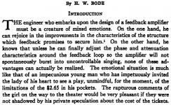
Bode comes alive as a real person here, with a nice sense of humor. Also note the great command of the English language.
Jan
Bode comes alive as a real person here, with a nice sense of humor. Also note the great command of the English language.
Jan
Attachments
Last edited:
try these models <snip>models</snip>
Thanks! Unfortunately using these KSA992/KSC1845 models raises the THD 20 by ~20dB 😱 ...
1. Ssassen_Rout graph - filmed by applying a signal to the amplifier output through an 8 ohm resistance. This is the common way to measure the output impedance of an amplifier. Output impedance is calculated using the formula: Rout = RL * Vout / (Vin-Vout)
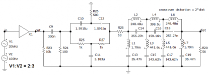
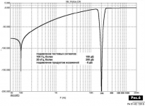
2. 2. Switching distortion is measured using a specially designed filter for this purpose. A complex signal of 100 Hz and 20 kHz is fed to the amplifier input. The filter cuts out these signals and at the output of the 50 Ohm matched filter we get the distortion products as shown in the Ssassen_cross-dist graph.
3. 3. Graph Ssassen_20kHz-spectr - the result of measuring the spectrum in the fourth period.
Alright, but as I have never generated these type of graphs before, what's your verdict? As I'm sure you have compared a wide variety of amplifier topologies judging from the other topic?
Yes it does, just include both loops (global and compensation) in a simulation. It was long time ago shown that TMC is mathematically equivalent with TPC plus a lead compensation, there's nothing that would make TMC better than TPC, other then some eye candy illusion. Everything else being equal, both can deliver the same amount of loop gain.
Yes, but what I was getting at is that if I wire the compensation (global and compensation) for TPC you'll get a peak midband, around 1kHz in this case, a peak that isn't there with (E)TMC, and yes, I'm scaling parts values to arrive at a similar OL and CL gain plot etc.
I positively love these sort of replies, as they serve as a reminder that every design is a compromise, a careful balancing act of weighing the requirements we set for a particular design and how far we're able to push a certain topology before it starts to fall apart.
I've not seen, nor have I tried, anything higher than 3rd order loops in discrete amplifier design, I'm sure designing such loops becomes increasingly difficult not just from a mathematical perspective, but also the practical, as the transition from a purely simulated design to a practical one, with all the parasitics and inductive and capacitive coupling, would be challenging I'm sure.
a) Brings back memories of the ExtremA class A amplifier, a project I started with Bruno Putzeys about 15 years ago. Bruno quickly zeroed in on a good topology, a full balanced, folded cascode, bridged configuration. With a good 250W of idle dissipation we did arrive at 100W/8R at vanishingly low THD scores, the size and power consumption of that design wasn't all too practical though.
b) Frankly circuit symmetry has not appealed to me much, as it cancels just the even harmonics and although the resulting THD can be made to be lower than a comparable asymmetric design, I find the uneven harmonics less pleasing to my ears. On top of that the parts count grows substantially and I'm just a sucker for simple and elegant design. But yes, you made a perfectly valid point.
Amen! I think we've all designed amplifiers in the simulator with <1ppb distortion that due to practicalities would never work IRL, I still believe it is an art and requires a lot of know-how and patience to get anywhere near that number IRL.
And to push this even further, for any compensation order (say 1 for Miller, or 2 for TMC or TPC, or 3 for Cherry NDFL), and given an amplifier open loop unity gain frequency, the maximum amount of available loop gain depends only on the compensation order. This is to say that extra loop gain can be obtained either by increasing the compensation order, or by increasing the open loop unity gain frequency. Alternatively, any push to get more loop gain by increasing the unity loop gain frequency comes with a stability margin penalty. Otherwise said, you can't have the cake and eat it too.
I've not seen, nor have I tried, anything higher than 3rd order loops in discrete amplifier design, I'm sure designing such loops becomes increasingly difficult not just from a mathematical perspective, but also the practical, as the transition from a purely simulated design to a practical one, with all the parasitics and inductive and capacitive coupling, would be challenging I'm sure.
And to push it one more time, Cherry showed a long time ago that there are exactly three ways to lower an amplifier distortions:
a) increasing the bias, so that active devices are in a more linear region (this is the Class A principle),
b) use distortion cancellation (for example: use circuit symmetry wherever possible, to cancel the even harmonics), and
c) use negative feedback (including local feedback).
a) Brings back memories of the ExtremA class A amplifier, a project I started with Bruno Putzeys about 15 years ago. Bruno quickly zeroed in on a good topology, a full balanced, folded cascode, bridged configuration. With a good 250W of idle dissipation we did arrive at 100W/8R at vanishingly low THD scores, the size and power consumption of that design wasn't all too practical though.
b) Frankly circuit symmetry has not appealed to me much, as it cancels just the even harmonics and although the resulting THD can be made to be lower than a comparable asymmetric design, I find the uneven harmonics less pleasing to my ears. On top of that the parts count grows substantially and I'm just a sucker for simple and elegant design. But yes, you made a perfectly valid point.
So for an audio amplifier performance targets, there's not much room to wiggle while keeping the stability margins in control, avoid building a Class A winter heater, and also keep other practicalities under control (clipping response, etc...).
Amen! I think we've all designed amplifiers in the simulator with <1ppb distortion that due to practicalities would never work IRL, I still believe it is an art and requires a lot of know-how and patience to get anywhere near that number IRL.
Also note the great command of the English language.
It reads more like a book than a technical paper, imagine having him as a professor lecturing in uni, I'm sure he would have done a great job with students enjoying the lecture.
Some remarks to circuit symmetry: Adding a comlementary input differential amplifier to achieve "perfect symmetry" just doubles the open loop gain. This may be achieved by simpler means and thus is not worth the additional circuit complexity imho.
Another issue is asymmetric distortion caused by improper layout - not to be seen in the simulator. This is what I experienced with my first LatFET layout and I was reminded that each half wave of the bridge generates maximum asymmetric distortion, like any rectifier does. Summing both half waves cancels these, but the slightest physical imbalance of this summing node will show increased H2, H4 etc. Following this, asymmetric distortion measurement can reveal some layout weakness you were not aware before....
Another issue is asymmetric distortion caused by improper layout - not to be seen in the simulator. This is what I experienced with my first LatFET layout and I was reminded that each half wave of the bridge generates maximum asymmetric distortion, like any rectifier does. Summing both half waves cancels these, but the slightest physical imbalance of this summing node will show increased H2, H4 etc. Following this, asymmetric distortion measurement can reveal some layout weakness you were not aware before....
Thanks for joining the discussion! And yes, that's something I certainly plan to explore, I already hinted at it in post #29.
Simplicity and elegance, feedback wanted! - post #29
P.s. Edmond, didn't a whole bunch of (principle) ETMC schematics disappear at some point due to a forum hiccup, all pertaining to your ETMC approach? Did anyone ever recover those? If so it would perhaps be interesting to post them here?
Bunch?
Hi Sander,
As far as I can see in my own files, I've posted only two versions of ETMC on this forum.
Cheers,
E.
Hi Sander,
As far as I can see in my own files, I've posted only two versions of ETMC on this forum.
Cheers,
E.
I hope this is not the only amp model you have in the simulator. You can make similar measurements yourself and evaluate the level of this development in comparison with others. This experience will be useful to you more than once. With regard to measuring IMD, this is a standard measurement procedure. Harmonic levels are presented in two forms: voltage and dB.Alright, but as I have never generated these type of graphs before, what's your verdict? As I'm sure you have compared a wide variety of amplifier topologies judging from the other topic?
Attachments
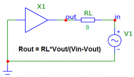
The formula: Rout=RL*Vout/(Vin-Vout) is certainly not incorrect per se, but I would make two remarks: Rout can be useful, but for general information Zout has more value.
In the case of an amplifier, the numerical values of Rout and |Zout| can be quite different for a number of reasons. For a SS amplifier for example, the NFB often results in a mostly inductive Zout.
The output impedance can be derived more easily with: Zout=Vout/I(RL), and if needed Rout can be extracted by looking at the real part of Zout
Or since you are looking for the small signal Zout, short the amp input to ground, use an 1A current source to inject in the output node (this is also the phase reference), do a AC sweep, V(out) is exactly Zout. Plot Re{Zout} and Im{Zout}, done, aren't simulators convenient. This is a direct result of the superposition theorem, no other assumptions.
That's not uncommon, as this counts for me too. Lost so many years was lost this nice paper to me, but regained now....Upon reading it I recognized the first para, so I probably have seen it before, can't remember when. The old memory decreases with age I guess....
Much appreciated!
Shouldn't be a statue be erected for Bode?
- Home
- Amplifiers
- Solid State
- Simplicity and elegance, feedback wanted!