The well-known phono preamps Shure M-64 and Dual TVV-47 were also on 2 transistors in each channel.


Wouldn't a simple resistor of 1500*120/3420 = 52.6 k (or even better 47 k) also do? Why that opamp?
Best regards!
I'm not the designer of this circuit, but I know the technique. It's meant to reduce noise. As far as I know, it was invented in 1939 by W. S. Percival and W. L. Horwood, but never got very popular for phono preamplifiers. It is used a lot in low-noise amplifiers for receivers, though.
In fact, the earliest application in phono amplifiers I know of is the Hoeffelman and Meys circuit from 1978, see posts 69 and 70 of https://www.diyaudio.com/community/...ono-stage-85-dba-sn-ratio.387375/post-7055871 Their circuit does not include RIAA correction.
I've explained the idea behind it in this article, which also shows a discrete phono preamplifier design, figure 5. Mind you, one of the sections of the gain switch is drawn in the wrong state in figure 5.
"Noise and moving-magnet cartridges", Electronics World October 2003, pages 38...43, https://worldradiohistory.com/UK/Wireless-World/00s/Electronics-World-2003-10-S-OCR.pdf
The 1939 article is: W. S. Percival, "An electrically "cold" resistance", The Wireless Engineer, Vol. 16, May 1939, pages 237...240,
https://worldradiohistory.com/UK/Experimental-Wireless/30s/Wireless-Engineer-1939-05.pdf
Last edited:
Enjoyed reading this. Wealth of info.
https://web.archive.org/web/2012080....com/background/riaa/uk_riaa_background_1.php
https://web.archive.org/web/2012080....com/background/riaa/uk_riaa_background_1.php
The story about that 50 kHz is incorrect according to Wikipedia, https://en.m.wikipedia.org/wiki/RIAA_equalization#The_Mythical_'Neumann_pole'
I do wish people would stop talking about the ‘Neumann Pole’. It’s been thoroughly debunked by Self, Gary Gallo and others. As explained elsewhere, the input signal to the cutter heads is bandwidth limited because you want to limit dissipation in the heads. This has nothing to do with EQ.
It may be some confusion arose because on all active RIAA amps, you cannot get full conformance at HF (means a fraction of a dB too much gain in the top octave) as Lipshitz explained in his paper. The simple solution to this is to place a passive pole after the EQ amp at 80 to 120 kHz. LTSpice is great for optimising this. This may have been taken up by designers as the mythical ‘Neumann pole’ and that’s how the whole thing became folklore.
The Williamson inverse RIAA, used for decades to test RIAA EQ preamps has no Neumann pole and Lipshitz’s EQ equations similarly have no reference to this.
I am confused when reading this link.
http://waynestegall.com/audio/riaa.htm#mozTocId495677
Here as in many other places they show a 60 DB gain at 40 or 50 hz.
Then in the above link
https://en.m.wikipedia.org/wiki/RIAA_equalization#The_Mythical_'Neumann_pole
The graph shows 20 DB gain.
Im confused which is right / better 20db or 60 db at 40-50 Hz. Why this confusion. I know there are various standards over the years. It does not help when such topics are being covered and no mention of which standard they are referring to is mentioned.
A moving-magnet phono preamplifier typically has a gain of roughly 40 dB at 1 kHz, 60 dB at 20 Hz. A moving-coil phono preamplifier typically has a gain of roughly 60 dB at 1 kHz, 80 dB at 20 Hz. The Wikipedia graph just shows the gain normalized to the value at 1 kHz.
When you shift the whole curve up or down, you just make the sound louder or softer. It doesn't change the flatness of the frequency response from the input of the recording RIAA correction network at the record pressing plant to the output of your phono preamplifier.
When you shift the whole curve up or down, you just make the sound louder or softer. It doesn't change the flatness of the frequency response from the input of the recording RIAA correction network at the record pressing plant to the output of your phono preamplifier.
Found this on another thread.
The plan is to enter up each of these in LTSpic or Micro Cap. Ive gotten up to the point where I can create the modells. May need help in analysing the results.
.png")
The plan is to enter up each of these in LTSpic or Micro Cap. Ive gotten up to the point where I can create the modells. May need help in analysing the results.
That's the one without RIAA correction I referred to in post #23. R2 could be replaced with a RIAA correction circuit, though. Another peculiarity is that it can't handle much output loading, as it affects the input impedance.
Last edited:
The story of the restoration of the SHURE M64 phono preamp - https://forum.polkaudio.com/discussion/194860/shure-m64-phono-tape-preamp
.............
Reason for this post.
1. Just in case somebody is every looking for a very simple RIAA transistor circuit.
2. If any member has a collection of Transistor based RIAA schematics they can throw up. To compare to this.
3. Any obvious hack / mods improvements to this design.
.......
Related to OP #2
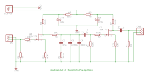
Attached is a four-transistor RIAA used by Sony in their TA-f5a, circa 1978. Sharing a few traits with the Self design in post#1. Q3 has no bootstrap and the collector resistor has been replaced by a CCS.
Probably Q4 and associated components could be replaced by a 10mA CCS.
The 1M5 resistor is a synthesized 50k load - its driven in antiphase to the input signal such that it looks like an impedance of 50k or so, but with a lot less current noise than a 50k resistor. You can also think of it as anti-bootstrapped, thus converting a high impedance to a low effective impedance.Wow, what an effort! I guess the first, discrete part could be substituted by a JFET input opamp, couldn't it? Anyway, what defines the resistive part of the cartridge load?
Best regards!
interesting circuit-topology. Concerning the input load R101 (usual values between 47K and 56K) so as C102+R102 in serial configuration (usual are only C - values between 100p and 220p) the question arises whether this is only suitable for a specific MM pickup model from Sony.Related to OP #2
Attached is a four-transistor RIAA used by Sony in their TA-f5a, circa 1978. Sharing a few traits with the Self design in post#1. Q3 has no bootstrap and the collector resistor has been replaced by a CCS.
Probably Q4 and associated components could be replaced by a 10mA CCS.
View attachment 1196166
L101 and R117 are parts for damping radio interference effects (unwanted SW reception) not often to find - go to
https://www.diyaudio.com/community/...ed-reception-of-broadcast-sw-stations.146351/
and
https://forum.audiogon.com/discussions/radio-interference-on-my-phono-stage
maybe for this reason R102 was introduced additional to C102.
But I don't know exactly. Maybe anywhere is a circuit description in detail concerning this parts around this kind input load.
The phono stage of NAD's model "3130" (integrated amplifier) also use an small inductance with resistor in parallel in it's four transistor phono stage. But without an additional serial resistor at the 100p capacity for input load - go to page 9 under
https://www.fabcollectibles.com/pdf/audio/receivers-amplifiers/nad-3130-service-manual.pdf
"interesting circuit-topology. Concerning the input load R101 (usual values between 47K and 56K) so as C102+R102 in serial configuration (usual are only C - values between 100p and 220p) the question arises whether this is only suitable for a specific MM pickup model from Sony."
Seen from a signal point of view, R101 & R103 are in parallel, thus loading is 50K. Nothing unusual here 😉
The "filter" C102+R102 should be seen as in serial with L101 also. Simulate it in LT, and see what it does 😉
Seen from a signal point of view, R101 & R103 are in parallel, thus loading is 50K. Nothing unusual here 😉
The "filter" C102+R102 should be seen as in serial with L101 also. Simulate it in LT, and see what it does 😉
Last edited:
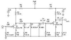
Today Im thinking why even have one transistor.
Lets see how simple we can go. i.e. passive RIAA.
Must have read over 200 pages.
But I like this one the best. It goes without saying. That I will have to enter up all of these in spice. And then the real work starts. Im still stuck at thinking about the input signal to the spice modell. Should I go with a simple mv sine wave. Or do I use one of the fancy circuits people have made to simulate a MM cart.
So much info to process so little time. But its all fun. When you learn something new everyday.
https://crude.axing.se/riaa-tweaks.html
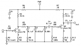
Another simple 3 transistor MM phono stage is the High Octane Phono preamp. Well recommended!
Worth reading also the LinearAudio article in Vol. 06!
cheers, Daniel
Worth reading also the LinearAudio article in Vol. 06!
cheers, Daniel
In post 32 I claimed that the Sony had some common traits with the Self design in the OP.
Seems I was fooled by the style of drawing, not looking at the actual topology.
Here is another discrete, this one from TNT-audio
https://www.tnt-audio.com/clinica/indiscreet.html

Seems I was fooled by the style of drawing, not looking at the actual topology.
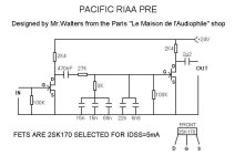
As simple as it goes with passive EQ, that must be the Pacific RIAA with JFET as per post #22 above..........Lets see how simple we can go. i.e. passive RIAA...........
Here is another discrete, this one from TNT-audio
https://www.tnt-audio.com/clinica/indiscreet.html
- Home
- Source & Line
- Analog Line Level
- Simple Transistor based RIAA