I'm not sure that I believe the model's bias conditions for a 12AX7, but that can be adjusted later if necessary. And, are you committed to a B+ of 300 volts? Could you get more? Linearity gets better with higher B+, and it's cheap and easy performance improvement, if possible.
Big FETs mean big capacitances, which means big signal currents to drive them, which means big idling current through the follower. Paralleled sections of type 6SN7 (and its family) or type 5687 would allow 15-20mA, which is a good start. Triode connected type EL84 would allow 30-40mA and makes an excellent follower. Other button based output valves are cheaper and available in lifetime quantities, especially the Russian ones. (Don't wait, though.)
*All* cathode followers need a cathode stop, sometimes called a build-out resistor. This should be connected directly to the cathode's socket pin, like a grid stop. Do not skip this step. Maybe start with 100R.
YOS,
Chris
i have only 295v i cant get more.I'm not sure that I believe the model's bias conditions for a 12AX7, but that can be adjusted later if necessary. And, are you committed to a B+ of 300 volts? Could you get more? Linearity gets better with higher B+, and it's cheap and easy performance improvement, if possible.
think i start from 12BH7Big FETs mean big capacitances
thanks Chris
Member
Joined 2009
Paid Member
FET capacitance is a non-issue when it is used in the way we are talking about; you will find only positive comments about this approach and especially it being very much superior to any tube alternatives. After many years of reading about this I’ve never found an objection that has survived, except for the perfectly acceptable ‘excuse’ of “but I just want to use a tube because that’s what I want”.
From your collection, I would choose the tube with highest transconductance for the follower. This means do not use the ‘AX7. The ‘AU7’ would be much better.
From your collection, I would choose the tube with highest transconductance for the follower. This means do not use the ‘AX7. The ‘AU7’ would be much better.
Last edited:
I tend to agree with you, regarding the transistor follower, it just seems like another power supply is needed.FET capacitance is a non-issue when it is used in the way we are talking about; you will find only positive comments about this approach and especially it being very much superior to any tube alternatives. After many years of reading about this I’ve never found an objection that has survived, except for the perfectly acceptable ‘excuse’ of “but I just want to use a tube because that’s what I want”.
From your collection, I would choose the tube with highest transconductance for the follower. This means do not use the ‘AX7. The ‘AU7’ would be much better.
do you have simple schema for that?
thanks
Attachments
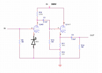
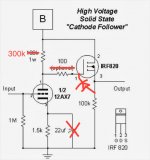
Does the following circuit meet the requirements of 20ma?Big FETs mean big capacitances, which means big signal currents to drive them, which means big idling current through the follower. Paralleled sections of type 6SN7 (and its family) or type 5687 would allow 15-20mA, which is a good start. Triode connected type EL84 would allow 30-40mA and makes an excellent follower. Other button based output valves are cheaper and available in lifetime quantities, especially the Russian ones. (Don't wait, though.)
the IRF820 as follower can do this job?
My take on it since you have 12AX7 and 12AU7 already.
Great, thank you very much

Attachments
"The MOSFET is loaded with 100k - the Zout will be almost as high as with a 12AX7, no?"
Not from the source, that gives 1/gm output resistance.
http://web.mit.edu/6.012/www/SP07-L20.pdf
Needs a 20V Zener clamp across the G-S for protection.
Not from the source, that gives 1/gm output resistance.
http://web.mit.edu/6.012/www/SP07-L20.pdf
Needs a 20V Zener clamp across the G-S for protection.
Last edited:
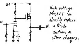
The 12AX7 stage can (and therefore should) have a much higher plate load resistor, maybe 300K Ohms, for best linearity and output swing. Easily done since direct coupled to a hi-Z gate; limited only by need to drive some parasitic capacitance.
MOSFETs make a convenient follower, and have higher transconductance than any practical vacuum valve, but a couple of caveats:
First, as folks have already said, their gate junction is fragile (super-duper thin insulating layer), and must be protected from over-voltage, even in handling! Wrap a bare wire around all three leads and solder a 12 Volt Zener from gate to source, right on the pins. This will allow you to handle it without special work mats and other voodoo.
Second, it'll need some serious heat sinking to dissipate enough power to be useful. 300 Volt B+ supply, half of it across the MOSFET, times 20mA (an absolute minimum IMO) is 3 Watts. 50mA will be 7.5 Watts.
3) All "cathode" followers need a stop resistor, mounted as close to the device as possible. They're a high feedback stage with an inductive output characteristic, so love to oscillate with a high enough Q capacitive load. The stop resistor damps this Q. Folks always tend to skip this important part, and then complain that cathode followers "sound bad". Either their scopes can't show the bursts of parasitic oscillation, or they haven't looked. Nuf said.
Without defining the load you need to drive, you can't know how much idling current you'll need. So that's the first step. If you research the topic of "slew rate" you'll get an idea of the interrelation of available driving current and load capacitance, and you can decide how much overhead, or margin, you're comfortable with. I'd guess that you're not planning to run loop feedback from the output of the final VFET, so you can cut this margin way down safely.
YOS,
Chris
Member
Joined 2009
Paid Member
FET followers are, of course, a popular option and they run off the same power supply as the tubes. Here’s a good thread that discuss the merits of particular FET choices. And you can add a zener diode to protect the FET.
"PowerDrive": how to choose the right MOSFET part?
"PowerDrive": how to choose the right MOSFET part?
ExcellentWhat is Gain Structure?
thanksFET followers are, of course, a popular option and they run off the same power supply as the tubes. Here’s a good thread that discuss the merits of particular FET choices. And you can add a zener diode to protect the FET.
guess right. 100ohm grid stopper is a must.I'd guess that you're not planning to run loop feedback from the output of the final VFET
i order IRF820, I will build the circle and publish results.
Thank you all
Attachments
Last edited:
Member
Joined 2009
Paid Member
Excellent
thanks
guess right. 100ohm grid stopper is a must.
i order IRF820, I will build the circle and publish results.
Thank you all
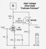
sounds good, don’t forget to heatsink that FET of course, and slap an output cap with 100k+ to ground after the cap to keep high voltage dc confined to the preamp.
Last edited:
I wasn't clear enough about the source stop resistor. This is *another* stop resistor, in addition to the gate stop. It's mounted, just like the gate stop, right up close and personal to the MOSFET itself, in the signal output lead. 100R would be a good starting point.
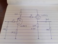
Your circuit shows about 1.5mA idling current - are you sure that's enough?
All good fortune,
Chris
Your circuit shows about 1.5mA idling current - are you sure that's enough?
All good fortune,
Chris
- Status
- This old topic is closed. If you want to reopen this topic, contact a moderator using the "Report Post" button.
- Home
- Amplifiers
- Tubes / Valves
- simple preamp from half 12ax7