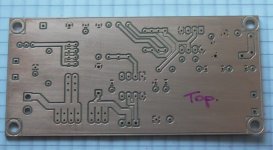
Nice looking PCB in #941, congratulations miklos! The drill holes appear to be perfectly aligned and I see at least 3 different drill sizes. So I will guess that a computer controlled drilling machine was used, instead of a human machinist operating a drill press manually?
Well done.
edit- post#103 shows a four-stage stuffing guide for V.4 but it seems you managed to plot the top silkscreen gerber file in the meantime. good show.
Well done.
edit- post#103 shows a four-stage stuffing guide for V.4 but it seems you managed to plot the top silkscreen gerber file in the meantime. good show.
Last edited:
Thanks Mark, and thanks again for the design.
Yes, it was a LPKF circuit board plotter, but I only have a limited number of dill sizes.
Yes, it was a LPKF circuit board plotter, but I only have a limited number of dill sizes.
Could you add that to post1 so that others can find it?Nice looking PCB in #941, congratulations miklos! The drill holes appear to be perfectly aligned and I see at least 3 different drill sizes. So I will guess that a computer controlled drilling machine was used, instead of a human machinist operating a drill press manually?
Well done.
edit- post#103 shows a four-stage stuffing guide for V.4 but it seems you managed to plot the top silkscreen gerber file in the meantime. good show.
It's already in post #1; that is how I found it this morning. See red arrow below.Could you add that to post1 so that others can find it?
_
Attachments

Hi Mark,
you still have Quasimodo V4 Boards for sale? I would interest on 2 Boards.
regards Walter
you still have Quasimodo V4 Boards for sale? I would interest on 2 Boards.
regards Walter
Walter, please see post #1 in this thread, particularly the paragraphs that begin with "EDIT 1" and "EDIT 3".
I got a complete kit from diyAudio member dsolodov recently and I'm perfectly happy!
Just follow Marks build instructions and failure rate will be zero 🙂
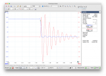
I have used/tested the circuit for a couple of different transformers and it works very nicely. With a large toroid (800VA, 2x21V) I however get a low optimal value for R1 (around 10R).
I have attached two screen shots. The first is with the pot unmounted and the second is with the pot in at 10R. Caps are Marks recommended values. Blue is the Quasimodo mosfet gate potential and red is the voltage across the TX secondary.
Just follow Marks build instructions and failure rate will be zero 🙂
I have used/tested the circuit for a couple of different transformers and it works very nicely. With a large toroid (800VA, 2x21V) I however get a low optimal value for R1 (around 10R).
I have attached two screen shots. The first is with the pot unmounted and the second is with the pot in at 10R. Caps are Marks recommended values. Blue is the Quasimodo mosfet gate potential and red is the voltage across the TX secondary.
Attachments

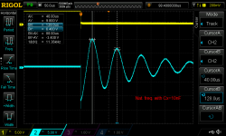
NicMac, the edge you want to trigger your scope upon, is the rising edge of the MOSFET gate waveform (or the falling edge of the MOSFET drain waveform).
See attached image, which I copied from post #298. The yellow trace is the drain of the MOSFET. The blue trace is the voltage across the transformer secondary. Notice that the transformer waveform steps down (when the MOSFET turns on) and then rings.
_
See attached image, which I copied from post #298. The yellow trace is the drain of the MOSFET. The blue trace is the voltage across the transformer secondary. Notice that the transformer waveform steps down (when the MOSFET turns on) and then rings.
_
Attachments
Beautiful build, Patrick. Congratulations! Since you've got a digital storage oscilloscope I don't think you'll ever need the frequency adjustment switches.
Looks like you implemented the power supply reverse protection diodes using at least one TO-220 part; that'll give you an extra couple hundred millivolts at the low end. You'll be surprised by how often you choose to run Quasimodo at 2.9 volts or less; it clarifies the waveforms delightfully.
I don't quite understand what's soldered into the footprint of the power-is-on LED; maybe the view is obscured.
You'll get slightly better performance if you solder the high current gate-driver IC directly to the PCB without any socket. At the enormous dI/dt this thing generates, that extra little bit of inductance really does matter. Particularly since you're not using the NTD4906 MOSFET with its incredibly small QGtot and world's best (Rdson * QGtot) figure of merit.
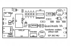
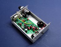
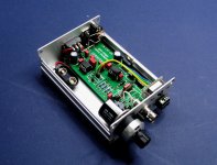
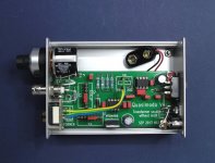
The TO220 device on the RHS of the top view is a 7809 regulator.
The power switch will switch between a 9V battery or external supply (unregulated).
The LED has long legs so that it goes right to the front panel, directly below the BNC socket.
I want to make sure it work first before perhaps removing the sockets.
And since this is not audio I am not looking for maximum performance. 😉
I cannot get the NTD4906 from Mouser. Appears to be no longer available.
Do you have a source for those ?
Patrick
One more lazy question.
If I have a Tx with multiple secondaries, should I leave them open or shorted (except for the one connected for measurement) ?
Cheers,
Patrick
If I have a Tx with multiple secondaries, should I leave them open or shorted (except for the one connected for measurement) ?
Cheers,
Patrick
Patrick, octopart.com tells me that Arrow, Verical, and Chip One Stop have got NTD4906's in stock. I don't know whether these businesses operate in Europe or ship there. Although if you don't care about the highest performance then you might very well decide you're perfectly satisfied with a socketed gate driver IC and a MOSFET whose QGtot isn't world champion. Me, I often use CheapoModo, whose penny pinching design connects three 2N7000s (TO92) in parallel, rather than having a power MOSFET. 3x2N7000 is definitely not world champion! However I find CheapoModo to be acceptable.
Using Quasimodo on a transformer with multiple secondaries is shown in Figure 13(d) of the Quasimodo Design Note, a pdf file attached to post#1 of this thread. The bold black lines in the Figure are "shorting bars" that you connect during QM testing.
I do think there will come a day when you pop open the case of your QM and connect a variable power supply to the 9V battery terminals using crocodile clips, so you can run Quasimodo on 2.9 volts. But hey I might be mistaken.
_
Attachments

Thanks.
2.9V can be supplied from external.
The 7809 should just past it through.
Or a battery clip with 2x AAA inside.
Patrick
2.9V can be supplied from external.
The 7809 should just past it through.
Or a battery clip with 2x AAA inside.
Patrick
Clever!2.9V can be supplied from external. The 7809 should just past it through.
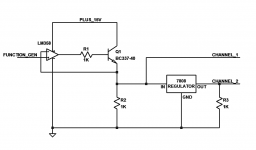
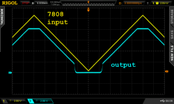
I built this up on my solderless protoboard this morning just to see it in action. I did not have any 7809 ICs but I did have a 7808 (8V output) so that's what I used.
A schematic of my protoboard circuit is shown in Figure 1. I drove the opamp with a 10 volt, 20 Hertz triangle wave. The opamp and NPN emitter follower copy this triangle wave onto the input of the voltage regulator. Then the output is monitored.
Figure 2 shows the waveforms. Input is yellow, output is blue.
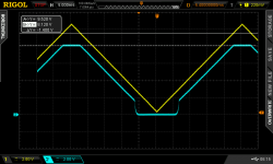
Figure 3 applies scope cursors to measure the regulated output voltage (dotted line @ 8.12V) and the regulator's IN-to-OUT voltage drop (1.4 volts).
So, if your 7809 regulator works like my 7808 regulator, all you need to do to get 2.9V out, is apply (2.9 + 1.4) = 4.3V input. Clever!
_
Attachments
If you look at the internal circuit of a typical series voltage regulator, this should come as no surprise.
🙂
Patrick
🙂
Patrick
NTD4906
RS has them on stock.
The TO220 device on the RHS of the top view is a 7809 regulator.
The power switch will switch between a 9V battery or external supply (unregulated).
The LED has long legs so that it goes right to the front panel, directly below the BNC socket.
I want to make sure it work first before perhaps removing the sockets.
And since this is not audio I am not looking for maximum performance. 😉
I cannot get the NTD4906 from Mouser. Appears to be no longer available.
Do you have a source for those ?
Patrick
RS has them on stock.
- Home
- Amplifiers
- Power Supplies
- Simple, no-math transformer snubber using Quasimodo test-jig