Uffff!!!!! What a fool I have been!!!
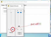
I have already discovered and fixed the problem. The problem was only that you had to disable the mute in the software tool: (image)
But every time I close and reopen hqplayer I have to go to disable it every time. But at least it works.
I have already discovered and fixed the problem. The problem was only that you had to disable the mute in the software tool: (image)
But every time I close and reopen hqplayer I have to go to disable it every time. But at least it works.
Attachments
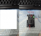
I connected as the attached picture but doesn't sound. Obviously Amanero to Amanero & DSC to Chronus & powered with 5V.
PCM2DSD to work needs from Amanero: Data, Bclk, LRck, Mclk, DSDOn, GND. And Mute it is pass from input to output. Look in post #68.I connected as the attached picture but doesn't sound. Obviously Amanero to Amanero & DSC to Chronus.
Last edited:

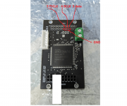
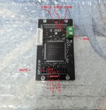
Input and output it is Amanero standard. See on pcb you have marked pins 1 and 10. Pin 3-data, 4-bclk, 5-lrck, 6-mclk, 7-dsdon, 11-mute.It's this input OK?
Attachments

Left channel no sound & right channel sounds distorted when Simple DSD modulator used. Bypassing the Simple DSD modulator left channel no sound but right channel sounds fine.
I will try, thanks.Input and output it is Amanero standard. See on pcb you have marked pins 1 and 10. Pin 3-data, 4-bclk, 5-lrck, 6-mclk, 7-dsdon, 11-mute.
Works thanks, a lot of more noise than converting DSD from Daphile.Input and output it is Amanero standard. See on pcb you have marked pins 1 and 10. Pin 3-data, 4-bclk, 5-lrck, 6-mclk, 7-dsdon, 11-mute.
It's possible because don't have it's own PSU + reg., it's sharing PSU+Ubib reg. with Cronus reclocker?
When you say 'a lot more noise' do you mean noise you easily can hear or noise you see on a FFT?
Also, do you have an oscilloscope to look at the DSD waveforms?
Also, do you have an oscilloscope to look at the DSD waveforms?
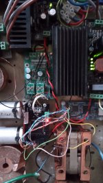
Looks like the connections go in the order of: USB board -> Simple DSD board -> Chronus board -> DAC. Is that right?
Other than the pic shows various things there may be some reason to be concerned about. Long wiring lengths, possible stray coupling between different parts of the circuitry, possibly mixed clock domains, etc.
Other than the pic shows various things there may be some reason to be concerned about. Long wiring lengths, possible stray coupling between different parts of the circuitry, possibly mixed clock domains, etc.
As i can see there are two domains, one amanero + pcm2dsd and second Cronus + dac.
For me better connect: Amanero in slave mode (mclk from cronus if cronus have clock 22/24MHz) -> cronus -> pcm2dsd -> dac.
Remember that pcm2dsd requires mclk from the 22/24MHz family.
For me better connect: Amanero in slave mode (mclk from cronus if cronus have clock 22/24MHz) -> cronus -> pcm2dsd -> dac.
Remember that pcm2dsd requires mclk from the 22/24MHz family.
Last edited:
Yes.Looks like the connections go in the order of: USB board -> Simple DSD board -> Chronus board -> DAC. Is that right?
Other than the pic shows various things there may be some reason to be concerned about. Long wiring lengths, possible stray coupling between different parts of the circuitry, possibly mixed clock domains, etc.
You are right, but is a lot of noise.
- Home
- Source & Line
- Digital Line Level
- Simple DSD modulator for DSC2