man, don't hesitate so much to use your brain
rails ripple shaving caps in all schematics are at least 100uF ...... you can have 0.1uF there too, if you like having so called bypass caps (bypass for bigger ones)
rails ripple shaving caps in all schematics are at least 100uF ...... you can have 0.1uF there too, if you like having so called bypass caps (bypass for bigger ones)
I had no idea what a rails ripple shaving cap was. In the photos I can see something that looked like five very small brown polypropylene caps. I saw one big cap that could be 100uF. Maybe all those blank caps in the schematic are connections to the same 100uF cap. See, I use brain! ☕man, don't hesitate so much to use your brain
rails ripple shaving caps in all schematics are at least 100uF ...... you can have 0.1uF there too, if you like having so called bypass caps (bypass for bigger ones)
Last edited:
you didn't convince me 
some reading for you, better to learn than to depend of asking same questions all the time:
in general - https://www.firstwatt.com/articles.html
especially https://www.firstwatt.com/pdf/art_lxmini crossover.pdf and https://www.firstwatt.com/pdf/art_diy biamp_6-24_ crossover.pdf and https://www.firstwatt.com/pdf/art_b1_man.pdf
Attachments

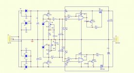
1. Correct like this? At least for 150Hz? View attachment 1082614
😂😂😂
good going man
so far you managed to be wrong at 100% efficacy
100uF/35VDC is what I would use, those are power supply smoothing capacitors, nothing to do with crossover frequency
if however you use very well stabilized power supply, you can omit those
this is example of power supply I use, its extremely quiet
https://www.ebay.com/itm/1648458817...ZIuZsMh6rbXCG9i4b9EM1rkA==|tkp:Bk9SR_jc5unWYA
https://www.ebay.com/itm/1648458817...ZIuZsMh6rbXCG9i4b9EM1rkA==|tkp:Bk9SR_jc5unWYA
Attachments
That is the problem of passive crossover.
One of the problems/limitations, but only on the HP side. Adason’s XO is compelling & elegant to me… after i get the 6-24 done i want to try it.
dave
I was under the impression that the sigma11 was the end all need for any other preamp power supply. The one you linked has an opamp in it. 😒 That is not a good look, but probably has no effect on the sound. And, since you recommend it, I am tempted to try it just to not have to solder all those 100uF/35V caps.
https://www.amb.org/audio/sigma11/
https://www.amb.org/audio/sigma11/
Sigma22, that is. 😛dual rails, you need that for this xover
so, look for dual rail regs
https://www.amb.org/audio/sigma22/
Okay, and why do I need dual rails? Don't answer. https://c.tenor.com/cTo__4DWgvYAAAAC/clint-eastwood.gif
Last edited:
maybe because adason drew schematic for dual rails supply?
though, trivial to rework (in several possible ways) to use single rail, but why bother?
though, trivial to rework (in several possible ways) to use single rail, but why bother?
Still processing, thank you!
Okay, I just need to buy these 100pcs of 2SK170BL from Jakarta. Matching those Jfets will be a fun task.
My plan for tonight, before ZM confused me with the dual rail conundrum, was to make an artistic impression of what this circuit would look like in real life with my amazing MS Paint skills. This might still happen.
Last edited:
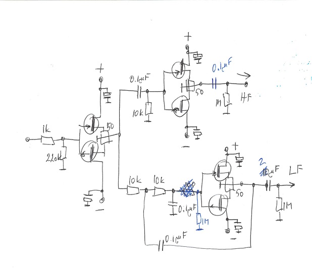
When I was experimenting with CRC upper path before the second buffer, I noted weird behavior sometimes, when I touched something, n channel jfet started to be fully open and I got 14.9 volts on the output. When I placed 1M ohm resistor from gates to ground, this never happened. So similarly, I placed the 1M on the low path too.
I am back for more. 😗 After reading the nice articles ZM suggested, I started to see a pattern. In the B1 article NP wrote about something called parasitic oscillation, and how a 1K resistor can prevent such bad mojo. Then I thought about your incident with 14.9V on the outputs and "sticking it to the rails". Maybe it would have been prevented if you had used a 1K resistor before the Jfets, like NP has since the dawn of time. Then even a bigger MAYBE, the 1M resistor on the Hi-pass and Lo-pass could be superfluous.Btw, if you see any obvious mistakes on the schematics, please let me know, I just drew it from other active crossovers I have seen around. Thanks.
Last edited:
well my friend , if you weren't trolling before, now you are
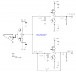
not just because you're not seeing why JFets could stick to rail (without better gates reference), in schematic from post #39, re-posted here
yes, gate stoppers are one way, gate shunt is the other way, but complementary buffer is and it is not same animal as same-sex-buffer

so, after you started seeing the pattern, indulge your self and read some more .......
not just because you're not seeing why JFets could stick to rail (without better gates reference), in schematic from post #39, re-posted here
yes, gate stoppers are one way, gate shunt is the other way, but complementary buffer is and it is not same animal as same-sex-buffer
so, after you started seeing the pattern, indulge your self and read some more .......
Reading this with interest. Can I confirm that the first component on the left of the schematic is the volume pot input from a preamp. And so the first actual components on the signal input on a PCB one may build for this would be the jfets/50r trimmer. ?
Thanks
Thanks
Hi.Long time has passed since this title opened but I need similar buffer but with gain but with 12db/oct minimum. Youtube decreases sound level by 14db so i think i need about 5x gain. I am planning to use opa627 for this but not sure if i should make gain before or after the crossover. I am planning to make before crossover so i can take out input buffer section too. And i asked to chatgpt and it told making inverting is better for gnd loops. So i can get the warmth and gain at the same time.
- Home
- Amplifiers
- Pass Labs
- simple active crossover