I have looked around but, could somebody please recommend a book with good treatment of transimpedance amplifiers?
OK, thank you Jeepee. I'll go and do some searching/reading. It so happens that all books by Jerald Graeme are missing from our library. 🙁
In the end, I'm not married to the transimpedance topology. I'm not sure that it's in any way superior to others. I might implement something simpler that I actually understand. We'll see how it goes after I take a stab at this transimpedance animal.
In the end, I'm not married to the transimpedance topology. I'm not sure that it's in any way superior to others. I might implement something simpler that I actually understand. We'll see how it goes after I take a stab at this transimpedance animal.
So the noise analysis holds only for the simple common-source amplifier.
Just a quick last response before I run for the train: no, it is perfectly valid for the overall amplifier too. The opamp indeed acts as virtual ground (actually virtual DC) input and hence fixes the voltage across the drain resistor. This converts the thermal voltage noise of the drain resistor to a current (voltage noise divided by drain resistor value). The overall noise contribution works out to be exactly the same.
In your lna the drain resistance is zero, so the noise grows to infinite?
Noise *referred to the input* (i.e. output noise divided by gain) goes to infinity. With zero drain resistor the "amplifier" has a gain of zero (zero, not zero dB = unity!). Hence the output noise (which is then entirely given by the opamp) gets divided by zero which is infinity. Of course with zero drain resistor the amp would not work at all because the DC conditions are off, but just as a theoretical example.
Samuel
but it's a useful rule of thumb and it can be shown easily using a vastly simplified JFET model.Luckily noise terms don't add like that.strange...I would have added the app. 0.15nVrt(Hz) noise from Rs directly to e_n_in.
First determine the output voltage: Ua = -gm*Ugs*Rd+UnRd
which is roughly proportional to Ugs
Ugs can be obtained by making up the equation for the left loop and setting Uo to zero (shorted input)
Uo=Unrg + Ugs +gm*Ugs*Rs+UnRs=0
=> Ugs=(-Unrg-UnRs)/(1+gmRs)
as you see the Johnson noise from Rs adds directly to equivalent input noise of the JFET.
Btw. Dennis Colin has used a circuit similar to your lna and he subtracted the noise of Rs from his measurements.
http://www.audioxpress.com/magsdirx/ax/addenda/media/colin2993.pdf
regards
Attachments
Hi Juergen,
Unless the formula I derived earlier is incorrect, to me the approximation is too inaccurate. For a gm of 20mS and Rd = 1500 the difference in noise with a 1R resistor and without is of 0.6pV/rtHz. This is quite far from the approximation.
Edit: and the comparison in Dennis Colin's example: with 10R and with 0R the difference is 6pV/rtHz.
ok, lets develop it further
with Ugs=(-Unrg-UnRs)/(1+gmRs) the output voltage gets
Ua=-gm*(-Unrg-UnRs)/(1+gmRs)*Rd+UnRd
divide it by the gain and you get the input related noise voltage
Ua/V=Unrg+UnRs+UnRd*(1+gmRs)/(gm*Rd)
with Unrg=rt(4*k*T*2/(3*gm), UnRs=rt(4*k*T*Rs) and UnRd=rt(4*k*T*Rd) you get:
Unin=rt(4kT)*(rt(2/(3+gm)+rtRs+rtRd*(1+gm*Rs)/(gm*Rd)
your (imho wrong) formula is:
e_ni = sqrt(4 k T) sqrt(1/gm + (1 + gm Rs)^2 / (gm^2 Rd))
is this from your formula or simulated?For a gm of 20mS and Rd = 1500 the difference in noise with a 1R resistor and without is of 0.6pV/rtHz
citation from the Collin's pdf:Edit: and the comparison in Dennis Colin's example: with 10R and with 0R the difference is 6pV/rtHz.
regardsThe thermal
noise of this 10Ω resistor (at +25° C)
is 0.4057nV/√Hz, which is RMS-added
(square root of sum of squares) to the
input-referred parallel FET noise.
Last edited:
Not simulated, but calculated using the formula.
Let's use the same notation so it's not confusing. Is rtRs = sqrt(Rs)?
The parantheses in this formula don't match.
Let's use the same notation so it's not confusing. Is rtRs = sqrt(Rs)?
The parantheses in this formula don't match.
Unin=rt(4kT)*(rt(2/(3+gm)+rtRs+rtRd*(1+gm*Rs)/(gm*Rd)
your right in both, rt=sqrt and I missed the paranthesis
Unin=rt(4kT)*(rt(2/(3+gm)+rtRs+rtRd*(1+gm*Rs)/(gm*Rd))
Unin=rt(4kT)*(rt(2/(3+gm)+rtRs+rtRd*(1+gm*Rs)/(gm*Rd))
Juergen, indeed I should have added the contribution of the source resistor Rs to the main formula. I will re-derive it below.
So, how does the equivalent input noise density e_ni varies in a simple common-source amplifier, like the circuit in post 383
http://www.diyaudio.com/forums/soli...e-low-noise-amplifier-lna-39.html#post2219606
Assume:
* Rs = 1 ohm
* B = bandwidth = 1Hz
* T = 290 degrees Kelvin
* input is connected to ground, hence source resistance is zero ohms
Definitions:
e_ni = equivalent input referred noise density
V_no = output noise density
A_v = voltage gain
gm = jfet transconductance
Req = equivalent jfet resistance = 1/gm
Req is actually lambda/gm and lambda between 0.2 and 0.8, typically approximated as 2/(3 gm) but for simplicity I set it to 1/gm. The trend in e_ni is not affected.
e_ni = V_no / A_v
A_v = gm Rd / (1 + gm Rs) = gm Rd / (1 + gm)
The output noise density is the rms sum of the amplified jfet self-noise and the drain resistor Rd noise.
V_no^2 = 4 k T Req (A_v)^2 + 4 k T Rd + r k T Rs
Let's work with squares for now, so divide V_no^2 by A_v^2 to get e_ni^2, and replace Req with 1/gm
e_ni^2 = V_no^2 / A_v^2 = 4 k T / gm + 4 k T Rd / A_v^2 + 4 k T Rs / A_v^2
Therefore:
e_ni = sqrt(4 k T) sqrt(1/gm + (1+gm)^2 / (gm^2 Rd) + Rs (1+gm)^2 / (gm^2 Rd^2))
So what was missing from the previous formula was the contribution of Rs to the total input referred noise was the thermal noise of Rs, i.e. sqrt(4 k T Rs) / Av.
Juergen, does this make more sense now?
Hm, one more thing. I'm thinking that the noise contribution of Rs should not only be taken as the contribution of a series resistor. Assuming that the input was shorted, then the noise generated by resistor Rs can be thought of as the input to a common-gate configuration. Then the noise of Rs should be first amplified by the voltage gain Av and then RMS added to e_ni. If we do that the final formula should be
e_ni^2 = sqrt(4 k T) sqrt(1 / gm + Rd / A_v^2 + Rs)
where
Av = -gm Rd / (1 + gm Rs)
e_ni^2 = sqrt(4 k T) sqrt(1 / gm + Rd / A_v^2 + Rs)
where
Av = -gm Rd / (1 + gm Rs)
You guys sure make it complicated. I can't criticize it, but you have to see the forest, as well as counting the trees.
John, I think it's nice to have the total noise formula, as well as the graphs. Looking at them one can see which factors have the greatest impact on the total noise.
In my opinion this IS seeing the forest. Trying to get the derivations right is just for correctness' sake.
In my opinion this IS seeing the forest. Trying to get the derivations right is just for correctness' sake.
we are making progress. The noise contribution of Rs plays a major part. The details should be understood, since some people still design phono preamps, with 2/3 of the input related noise not coming from the input transistors.
@ikoflexer: My network theory is probably more than rusty and I need to overthink the rms adding of noise sources.
But first things first:
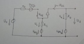
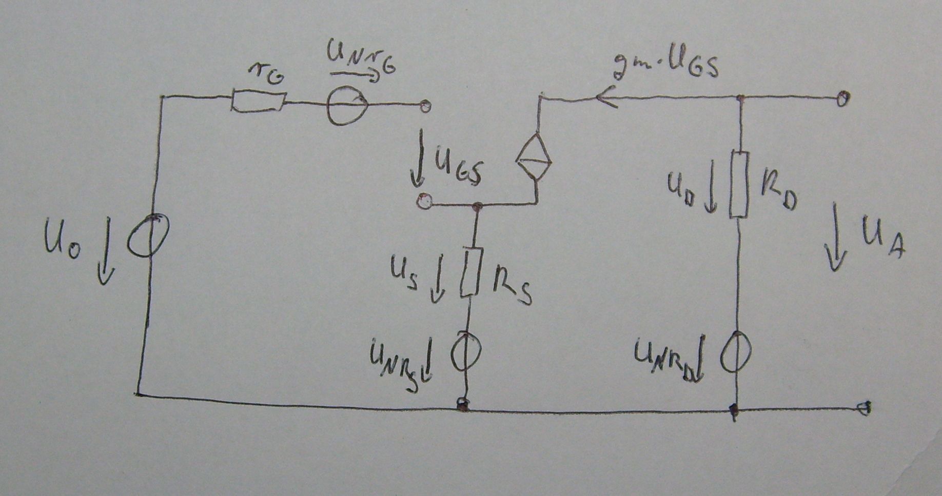
Do you agree on the equivalent circuit shown in post 405?
http://www.diyaudio.com/forums/atta...rete-low-noise-amplifier-lna-jfetrauschen.jpg
regards
@ikoflexer: My network theory is probably more than rusty and I need to overthink the rms adding of noise sources.
But first things first:
Do you agree on the equivalent circuit shown in post 405?
http://www.diyaudio.com/forums/atta...rete-low-noise-amplifier-lna-jfetrauschen.jpg
regards
Last edited:
Well, for me, it is like this. The effective input noise resistance is 2/3(1/gm) + Rs That is all there is to it, for j-fets.
Well, for me, it is like this. The effective input noise resistance is 2/3(1/gm) + Rs That is all there is to it, for j-fets.
Yes John, I think you just summarized my last equation. The voltage noise of both the equivalent resistance of the jfet channel and of Rs get amplified by Av, so the two of them can be combined as
Req = (2/(3gm) + Rs)
The only other voltage noise source is Rd and is in series. So the total output noise should be
eno = sqrt(4 k T Req Av^2 + 4 k T Rd)
which, referred to the input is
eni = eno / Av = sqrt(4 k T (2/(3gm)+Rs) + 4 k T Rd/Av^2)
Juergen, I'm ok with the picture you drew except, if the input is shorted, shouldn't Rg be gone? Also, in the formula you derive, you don't add the noise voltages using sums of square roots.
The current source amplifies its own noise, and it gets rms added to the rest. 🙂
The jfet current source noise calculation should be very similar to the above without the Rd term.
The jfet current source noise calculation should be very similar to the above without the Rd term.
- Home
- Amplifiers
- Solid State
- Simple 60dB discrete low noise amplifier (lna)