Oh, sorry, I meant to say the drain resistor Rd, which would have to be larger if the biasing of the jfet is lower. Did your 10% more noise estimate include the noise contribution of Rd?
My question regarding current noise was more about the second stage being an I-V converter, hence, the current noise of the first stage would directly influence the overall output.
My question regarding current noise was more about the second stage being an I-V converter, hence, the current noise of the first stage would directly influence the overall output.
Did your 10% more noise estimate include the noise contribution of Rd?
No. But remember: the larger the drain resistor, the lower its noise contribution at this node. That's why I wrote that "noise contribution from the first stage drain resistor is reduced" if we bias the input stage at lower current and proportionally increase Rd.
My question regarding current noise was more about the second stage being an I-V converter, hence, the current noise of the first stage would directly influence the overall output.
One cannot answer this question in general. You can calculate the approximate input-referred noise contributions as follows (gm = total input stage transconductance):
* In/gm (In = opamp current noise)
* En/Rd/gm (En = opamp voltage noise)
So depending on Rd and gm you need a different opamp. With low Rd (the case here) you need low voltage noise.
Samuel
OK, I know this is trivial for you, but I'll work it out so that it may help some other beginners. Please, somebody point out if there are mistakes.
We want to see how the equivalent input noise density e_ni varies in a simple common-source amplifier like the one in the first attached image.
Assume:
* Rs = 1 ohm
* B = bandwidth = 1Hz
* T = 290 degrees Kelvin
* input is connected to ground, hence source resistance is zero ohms
Definitions:
e_ni = equivalent input referred noise density
V_no = output noise density
A_v = voltage gain
gm = jfet transconductance
Req = equivalent jfet resistance = 1/gm
Req is actually lambda/gm and lambda between 0.2 and 0.8, typically approximated as 2/(3 gm) but for simplicity I set it to 1/gm. The trend in e_ni is not affected.
e_ni = V_no / A_v
A_v = gm Rd / (1 + gm Rs) = gm Rd / (1 + gm)
The output noise density is the rms sum of the amplified jfet self-noise and the drain resistor Rd noise.
V_no^2 = 4 k T Req (A_v)^2 + 4 k T Rd
Let's work with squares for now, so divide V_no^2 by A_v^2 to get e_ni^2, and replace Req with 1/gm
e_ni^2 = V_no^2 / A_v^2 = 4 k T / gm + 4 k T Rd / A_v^2
e_ni^2 = 4 k T (1/gm + Rd (1+gm)^2 / (gm^2 Rd^2))
Therefore:
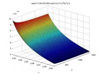
e_ni = sqrt(4 k T) sqrt(1/gm + (1+gm)^2 / (gm^2 Rd))
Now we can see in the equation of e_ni that as the value of Rd increases, e_ni decreases. However, it's not so easy to see how drastic the relationship is.
Took this formula and plotted it in matlab varying gm from 20mS to 90mS and Rd from 150R to 1k5. That's the second attached image.
We want to see how the equivalent input noise density e_ni varies in a simple common-source amplifier like the one in the first attached image.
Assume:
* Rs = 1 ohm
* B = bandwidth = 1Hz
* T = 290 degrees Kelvin
* input is connected to ground, hence source resistance is zero ohms
Definitions:
e_ni = equivalent input referred noise density
V_no = output noise density
A_v = voltage gain
gm = jfet transconductance
Req = equivalent jfet resistance = 1/gm
Req is actually lambda/gm and lambda between 0.2 and 0.8, typically approximated as 2/(3 gm) but for simplicity I set it to 1/gm. The trend in e_ni is not affected.
e_ni = V_no / A_v
A_v = gm Rd / (1 + gm Rs) = gm Rd / (1 + gm)
The output noise density is the rms sum of the amplified jfet self-noise and the drain resistor Rd noise.
V_no^2 = 4 k T Req (A_v)^2 + 4 k T Rd
Let's work with squares for now, so divide V_no^2 by A_v^2 to get e_ni^2, and replace Req with 1/gm
e_ni^2 = V_no^2 / A_v^2 = 4 k T / gm + 4 k T Rd / A_v^2
e_ni^2 = 4 k T (1/gm + Rd (1+gm)^2 / (gm^2 Rd^2))
Therefore:
e_ni = sqrt(4 k T) sqrt(1/gm + (1+gm)^2 / (gm^2 Rd))
Samuel Groner said:No. But remember: the larger the drain resistor, the lower its noise contribution at this node.
Now we can see in the equation of e_ni that as the value of Rd increases, e_ni decreases. However, it's not so easy to see how drastic the relationship is.
Took this formula and plotted it in matlab varying gm from 20mS to 90mS and Rd from 150R to 1k5. That's the second attached image.
Attachments

Good work! Now you could extend things by including opamp noise contribution and taking real JFET noise data rather than theoretical approximations (which become inaccurate towards Idss).
I'm off for some holidays now...
Samuel
I'm off for some holidays now...
Samuel
Thanks Samuel, and have a great vacation!
P.S. The rigorous calculation of the opamp noise contribution is a bit involved (being a transimpedance topology) but the least I can do is to add the Rf factor which seems to be the largest noise contribution in that topology. Sorry, I don't know what you mean by real JFET noise data, I don't have the setup to measure them (besides the trivial measuring of Idss).
P.S. The rigorous calculation of the opamp noise contribution is a bit involved (being a transimpedance topology) but the least I can do is to add the Rf factor which seems to be the largest noise contribution in that topology. Sorry, I don't know what you mean by real JFET noise data, I don't have the setup to measure them (besides the trivial measuring of Idss).
The formula including Rs would be
e_ni = sqrt(4 k T) sqrt(1/gm + (1+gm Rs)^2 / (gm^2 Rd))
Therefore, larger Rs, higher noise.
Hang on, I'll also show the relationship between noise and varying the JFET operating current Id. There was a discussion about this previously, but I'll show what the theory predicts.
e_ni = sqrt(4 k T) sqrt(1/gm + (1+gm Rs)^2 / (gm^2 Rd))
Therefore, larger Rs, higher noise.
Hang on, I'll also show the relationship between noise and varying the JFET operating current Id. There was a discussion about this previously, but I'll show what the theory predicts.
Well, we might as well plug in some values: gm = 0.02 mS, Rd = 1k5, and Rs 0R5, 1R, and 10R. The noise would be 0.9097nV/rtHz, 0.91nV/rtHz, and 0.9159nV/rtHz, respectively
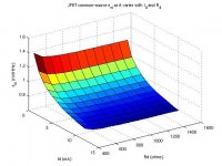
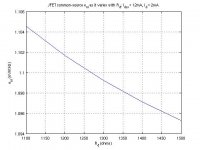
Here's another plot, of the same formula which assumes Rs = 1R. This time it shows the input referred noise density as it varies with the operating current Id = [1mA, 2mA, ..., 12mA], and with Rd = [400R, 500R, ..., 1500R]. Idss was assumed 12mA, and pinch-off voltage Vp was assumed 0.7V.
To get this note that the JFET transconductance is defined as:
gm = 2 sqrt(Id Idss) / Vp
so gm can be replaced in the e_ni formula above.
Notice how the noise decreases significantly as Id approaches Idss, and how if we fix Id, Rd does have an effect in that the noise lowers for higher Rd, but the effect is very small.
Note: all the above implies one fjet. For a parallel combination of jfets you can imagine that the gm (Id and Idss) is (are) larger, Vp stays the same.
Attachments
strange...I would have added the app. 0.15nVrt(Hz) noise from Rs directly to e_n_in.
Another question...In your lna the drain resistance is zero, so the noise grows to infinite? :?
regards
Another question...In your lna the drain resistance is zero, so the noise grows to infinite? :?
regards
I hate to say this, but you should get the 'overall view' of the nature of fets and not just crank out simulations. This will make the understanding easier and the direction for best performance more obvious.
strange...I would have added the app. 0.15nVrt(Hz) noise from Rs directly to e_n_in.
Luckily noise terms don't add like that.
Another question...In your lna the drain resistance is zero, so the noise grows to infinite? :?
regards
Zero? I don't know which circuit (post number) are you referring to?
well the drain is connected to a virtual earth node?
http://www.diyaudio.com/forums/solid-state/165961-simple-60db-discrete-low-noise-amplifier-lna-33.html#post2212242
http://www.diyaudio.com/forums/solid-state/165961-simple-60db-discrete-low-noise-amplifier-lna-33.html#post2212242
Last edited:
I hate to say this, but you should get the 'overall view' of the nature of fets and not just crank out simulations. This will make the understanding easier and the direction for best performance more obvious.
John, everyone gets to understand something in different ways. How is one to get the 'overall view' of the nature of fets if not also by understanding the basic formulas that describe the device? These simulations are nothing but a visualization of the noise formula, which, by the way, is only an approximate model of the noise if jfets. Seeing a trend in how the noise changes when other jfet operating parameters change help me, and I hope others too.
You can definitely not blame me for not implementing and measuring these circuits, because until now that's all I did. 🙂
Please help if you have something to clarify or fix. Me and many other newbies do appreciate your help. Well, I shouldn't speak for others, but I certainly have always appreciated your input.
well the drain is connected to a virtual earth node?
http://www.diyaudio.com/forums/solid-state/165961-simple-60db-discrete-low-noise-amplifier-lna-33.html#post2212242
The drain sees the current source of J10, J11, and R3, which has a high dynamic resistance.
which is ac-shorted by the virtual zero provided by the opamp circuit 😉The drain sees the current source of J10, J11, and R3, which has a high dynamic resistance.
regards
Ikoflexer, please read up on transimpedance amplifier "secrets".
Juergen is fully right, the input JFETs drain is terminated by virtually 0 Ohm. It does not see the CCS at all.
You need to understand that fact, it's blocking your progress...
Juergen is fully right, the input JFETs drain is terminated by virtually 0 Ohm. It does not see the CCS at all.
You need to understand that fact, it's blocking your progress...
OK guys, thanks, I will. So the noise analysis holds only for the simple common-source amplifier. Remember I said that doing the noise analysis for the transimpedance amplifier is not yet within my reach.
Any pointers on how to predict the noise of the entire circuit? Also, if I replace for now the current source with a resistor, even with the transimpedance stage next, would the noise analysis above hold?
Any pointers on how to predict the noise of the entire circuit? Also, if I replace for now the current source with a resistor, even with the transimpedance stage next, would the noise analysis above hold?
So what happens if we parallel N jfets in a common source amplifier. The usual answer people around here gave me was that the noise will be divided by sqrt(N). Let's use the above formula to see how the noise changes.
For one jfet
gm = 2 sqrt(Id Idss) / Vp
For N jfets the current is N times larger, but the pinch-off voltage Vp remains the same.
gmN = 2 sqrt(N Id N Idss) / Vp = N 2 sqrt( Id Idss) / Vp = N gm
So the gm of N identical paralleled jfets is N times larger than the gm of one jfet.
Since the equivalent resistance of one jfet is
Req = lambda / gm
then for N jfets
ReqN = lambda / (N gm)
The voltage gain of one jfet is
Av = - gm Rd / (1 + gm Rs)
and for N paralleled jfets is
AvN = - N gm Rd / (1 + N gm Rs)
The noise of one jfet in common-source configuration was derived as:
e_ni = sqrt(4 k T) sqrt(1/gm + (1 + gm Rs)^2 / (gm^2 Rd))
Replacing Req and Av results in the noise of N paralleled jfets:
e_niN = sqrt(4 k T/N) sqrt(1/gm + (1 + N gm Rs)^2 / (N gm^2 Rd))
So e_niN is not exactly equal to e_ni / sqrt(N), but the difference is not large.
For example, let's take 9 jfets each with gm = 20mS, Rd = 1k5, and Rs = 1.
The predicted noise of the circuit with one such jfet would be
e_ni = 0.92328 nV/rtHz
The usual approximation of 9 paralleled jfets would give us this number divided by 3, which is 0.30776 nV/rtHz.
Using the formula above we obtain
e_niN = 0.29966 nV/rtHz
There, not a big deal, I know, but whatever.
- Home
- Amplifiers
- Solid State
- Simple 60dB discrete low noise amplifier (lna)