None, zero, zip, nada, jack ****. Matching JFETs here is absolutely useless. Sorting for noise is a different story and I used my Quantech to sort the 2SK170 to 0.7-0.8nV/rtHz. No noise sorting for BF862.
You're using my name in vain, which is a mortal sin.
Summary
syn08, I've tried a little earlier your filter, without the LM317 part
because I used a regulated lab power supply. The noise was still
quite a bit higher than using batteries only.
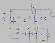
In an attempt to improve the PSRR and get rid of some of the RF junk I implemented this simple cap multiplier (Joachim, good suggestion!). Also added a common mode ferrite choke like those found in the psu of many CRT monitors. This filter made a difference in powering the circuit from the lab supply which is terribly noisy. It cleaned up most of the junk. The filter output impedance is dismal, so I may come up with some filter/regulator that's better than this one.
So you are suggesting that the Sziklay (current feedback) buffer is more noisy than a simple two stage emitter follower buffer and a common mode choke.
Man, you need to check your setup, this doesn't make any sense (both from a noise and output impedance perspectives). BTW, you are still stubbornly refusing to look at the several suggestions you got, to increase the amp PSRR, rather than relying on the power supply only.
So you are suggesting that the Sziklay (current feedback) buffer is more noisy than a simple two stage emitter follower buffer and a common mode choke.
Man, you need to check your setup, this doesn't make any sense (both from a noise and output impedance perspectives).
I've only reported what happened. Surely I made a mistake in implementing your buffer. Is there anything I should pay special attention to with this circuit?
Simulation is not reality, but it can give some indication about the two circuits. See the attached one versus the other, psrr and output impedance. I don't trust the noise simulation even more, so I left it out.
BTW, you are still stubbornly refusing to look at the several suggestions you got, to increase the amp PSRR, rather than relying on the power supply only.
No, don't be so quick to label. You said earlier that you're confident the problem is with the psu, so I tried to improve it. You also said I should change one thing at a time. I will get to those several suggestions to increase the PSRR, just can't afford to work 24h on this. BTW, what would be your preferred suggestion to improve the PSRR?
Attachments
Iko, I would put a resistor of 1K or so between the base-emitter junction of Q4. You have a potential problem point as you have starved off the drive transistor, and I am pretty sure it was shown somewhere that that configuration is not as quiet without the resistor.
Simulation is not reality, but it can give some indication about the two circuits. See the attached one versus the other, psrr and output impedance. I don't trust the noise simulation even more, so I left it out.
I have no idea what those simulated graphs are, but I do know you are comparing apples and pears. The double buffer has x10 larger caps (1000uF vs. 100uF). Even if you are a beginner, you are not that stupid not to realize that makes a lot of a difference. Otherwise, whatever you are doing in Spice, it is completely absurd to assert that an emitter follower can have a smaller output impedance (always about 1/gm) compared to a Sziklay pair (that multiplies the equivalent gm by the driver Beta, pretty much like a Darlington). Anyway, if the startup time is not an issue, just use 1F caps and you'll get even better results. BTW, simulation without parasitics is here pretty much useless.
Noise simulation results are excellent if the bipolar device models are modelling RB. Otherwise, they are exceedently optimistic. If RB is not modelled, then the emitter follower and the Sziklay pair should provide about the same noise performance (actually the Sziklay can be slightly worse).
EDIT: To add insult to injury, the double buffer has the output voltage depending on Beta. John is right about the BE resistor, if the output current is small.
Last edited:
I have no idea what those simulated graphs are, but I do know you are comparing apples and pears.
Took your circuit (without pre-regulation from your HPS 5.1. The simulation is AC analysis with the voltage source small signal AC amplitude set to 1. The plot should be a representation of the PSRR.
The double buffer has x10 larger caps (1000uF vs. 100uF). Even if you are a beginner, you are not that stupid not to realize that makes a lot of a difference.
It has nothing to do with intelligence, so please let's keep personal remarks out of the discussion. Attached is the plot with all caps (except for the 100nF) in the Sziklay buffer set to 1000uF. All 1000uF caps have ESR set to 0R1, the 100nF cap to 5 milliohm.
Otherwise, whatever you are doing in Spice, it is completely absurd to assert that an emitter follower can have a smaller output impedance (always about 1/gm) compared to a Sziklay pair (that multiplies the equivalent gm by the driver Beta, pretty much like a Darlington).
It's simple enough to plug it in yourself and see, absurd as it may seem. But just in case you'll blame LTSpice, I'll plug it into Orcad as well and plot it. I don't want to argue with you about this, I just thought it be instructive to have a look at the simulated PSRR of these simple circuits.
Anyway, if the startup time is not an issue, just use 1F caps and you'll get even better results. BTW, simulation without parasitics is here pretty much useless.
I left out the wire inductance/resistance in both circuits because I didn't think it would make that much of a difference, but OK, will try with it later. What other parasitics should I add?
Noise simulation results are excellent if the bipolar device models are modelling RB. Otherwise, they are exceedently optimistic. If RB is not modelled, then the emitter follower and the Sziklay pair should provide about the same noise performance (actually the Sziklay can be slightly worse).
I've been using bipolar models from Orcad for this simulation, but haven't checked if RB is modeled.
EDIT: To add insult to injury, the double buffer has the output voltage depending on Beta. John is right about the BE resistor, if the output current is small.
I'll try to tweak it as per John's suggestion.
Attachments
Iko, I would put a resistor of 1K or so between the base-emitter junction of Q4. You have a potential problem point as you have starved off the drive transistor, and I am pretty sure it was shown somewhere that that configuration is not as quiet without the resistor.
Thank you John, indeed, the resistor does help the bias of Q3.
I'd like to clarify something about PSRR and its relation to the graphs I posted above in response to
and to my hasty reply to it.
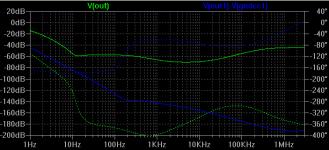
Technically the graphs are not exactly a representation of PSRR, but of 1/PSRR. However, I thought it was pretty obvious. Apparently it was not. So let me explain in detail.
The power supply ripple rejection (PSRR) is a measure of how well a circuit rejects ripple that enter via the power supply. By this definition high PSRR is good to have. For the case at hand this is measured in dB and is defined as:
PSRR = 20 log (Vin_ripple/Vout_ripple)
One can avoid complications by using Vin_ripple and Vout_ripple as the RMS of a sine wave of zero volts DC offset over the frequency range of interest. The logarithm is base 10.
For the simple filters shown in the posts above the input is the voltage source V1 and the output is clearly labeled. In LTSpice, if the small signal AC amplitude is set to some value X volts, running the AC analysis over a frequency range and then plotting the voltage at a node (e.g. out) in the circuit will show by default the line corresponding to
20 log V(out)
If X = 1 volt then the graph shown by LTSpice will be simply the plot corresponding to 1/PSRR. The same shape and magnitude in dB, except that it is shown in negative dB instead of positive. Although it's quite surprising to me that someone with a bit of experience in simulation couldn't see this, I have to say that I should have explained better the graphs I was showing. As a side note, when dealing with a regulator or filter of this type I prefer to see 1/PSRR and think of it as a measure of attenuation of the ripple that enters the circuit through the power supply.
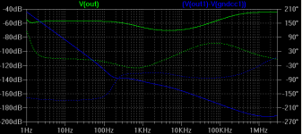
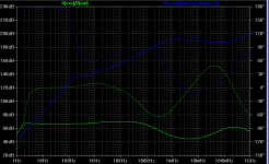
And to finish the example, attached is the graph of what I should have properly called PSRR for the two circuits in post 344. Note the symmetry wrt the x axis, same magnitude, different sign.
Unfortunately syn08 refuses to continue to be part of this discussion so I'm just writing this for everybody else who might care. Please do let me know if any of you can find errors with what I do.
Intuition aside, can someone clarify why the Sziklai pair circuit should have better ripple rejection than the other simple circuit?
I have no idea what those simulated graphs are
and to my hasty reply to it.
Took your circuit (without pre-regulation from your HPS 5.1. The simulation is AC analysis with the voltage source small signal AC amplitude set to 1. The plot should be a representation of the PSRR.
Technically the graphs are not exactly a representation of PSRR, but of 1/PSRR. However, I thought it was pretty obvious. Apparently it was not. So let me explain in detail.
The power supply ripple rejection (PSRR) is a measure of how well a circuit rejects ripple that enter via the power supply. By this definition high PSRR is good to have. For the case at hand this is measured in dB and is defined as:
PSRR = 20 log (Vin_ripple/Vout_ripple)
One can avoid complications by using Vin_ripple and Vout_ripple as the RMS of a sine wave of zero volts DC offset over the frequency range of interest. The logarithm is base 10.
For the simple filters shown in the posts above the input is the voltage source V1 and the output is clearly labeled. In LTSpice, if the small signal AC amplitude is set to some value X volts, running the AC analysis over a frequency range and then plotting the voltage at a node (e.g. out) in the circuit will show by default the line corresponding to
20 log V(out)
If X = 1 volt then the graph shown by LTSpice will be simply the plot corresponding to 1/PSRR. The same shape and magnitude in dB, except that it is shown in negative dB instead of positive. Although it's quite surprising to me that someone with a bit of experience in simulation couldn't see this, I have to say that I should have explained better the graphs I was showing. As a side note, when dealing with a regulator or filter of this type I prefer to see 1/PSRR and think of it as a measure of attenuation of the ripple that enters the circuit through the power supply.
And to finish the example, attached is the graph of what I should have properly called PSRR for the two circuits in post 344. Note the symmetry wrt the x axis, same magnitude, different sign.
Unfortunately syn08 refuses to continue to be part of this discussion so I'm just writing this for everybody else who might care. Please do let me know if any of you can find errors with what I do.
Intuition aside, can someone clarify why the Sziklai pair circuit should have better ripple rejection than the other simple circuit?
Attachments
Iko,
Looking at the circuits in post 344, it looks as if you labelled the DC input for AC analysis as 'AC 1'. I'm not familiar with LTSpice but some simulators replace the source with an ac source in such cases. Personally I always do this with two sources in series, one the DC source and the other the AC source; I can play with the ac without disturbing the DC input. Are you sure this worked as expected?
jd
Good point Jan, but in LTSpice the results are exactly the same when using two sources in series (one supplying the DC component and the other the DC component) or using one voltage source that has both DC and AC components defined. Orcad too, gave me the same result.
Hi Ikoflexer,
it does not surprise me that the simple stacked NPN's have a good PSRR.
Although the CM-choke colours the picture to some extent (maybe you can temporarily do away with it for a fair circuit comparison), two stacked devices will have a better PSRR than one.
From the supply point of view, Q1 (post #344) is an emitter followor.
The PSRR is roughly the ratio of collector impedance (ro in the hybrid-pi model) to the emitter follower output impedance (roughly 1/gm).
ro = VA/Ic, gm=40Ic. VA is the Early voltage.
So PSRR ~ ro/(1/gm) = ro*gm = VA/Ic * 40Ic = 40*VA
(beware, this is a gross simplification, to quickly determine the order of magnitude)
Looking in the spice models I found for VAF (the forward Early voltage):
D44H11: VAF=40.72V
2N5089: VAF=62.37V
BC850: VAF=73.4V
ZTX: VAF=1900V (?? unusual high value)
So for the stacked NPN topology we get:
PSRR Q2: 40*62.37 = 67.9dB
PSRR Q1: 40*40.72 = 64.2dB
Total PSRR = 132dB.
Looking at your graph, the flat section around 200-400Hz shows a PSRR of 138dB. Pretty close I'd say, for such a simple formula. (I guess that above that frequency range the CM-choke starts to dominate)
I did not analyse the Sziklai compound transistor carfully, but it looks like PSRR is determined only by Q3. Whatever ripple is present on the supply node 'Vcc' is forced onto the collector of Q3 by the "stiff" BE-juntion of Q4. So the PSRR of the compound looks to be the same as of Q3 alone, despite the clever feedback. Taking the simple formula again for Q3, PSRR = 20*log(40*73.4)= 69.4dB.
PS: why do you use 2 different NPN's in the stacked topology?
in case of a power supply circuit, we talk about 'line regulation' not PSRR! 
Anyway, the circuit seems to be overdone and I miss some clarity.
@ikoflexer:
You have build an amplifier prototype and have access to a decent analyser, as I understand.
What's the PSSR of your amp and what's the noise level of your batteries/power supply you want to tame with that third order low pass?
regards
Hey Iko. I was wondering if this might be topical:
SALE! Rare Ultraperm 80 Shielding Sheet-The Electronic Goldmine
BTW, has LTSpice been been consistent in its noise analysis? Can I trust LTSpice noise analysis?
- keantoken
SALE! Rare Ultraperm 80 Shielding Sheet-The Electronic Goldmine
BTW, has LTSpice been been consistent in its noise analysis? Can I trust LTSpice noise analysis?
- keantoken
Hi Jeepee,
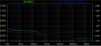
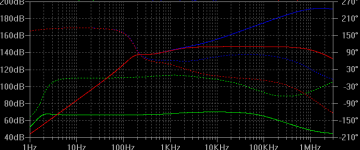
The green and blue lines in the attached plots are just like before, and for comparison, the red line which is the simulation of the cap multiplier without the choke.
Thank you for the sanity check calculations!
From all passive and active components in this little circuit the second position NPN seemed to have the most significant contribution to the self-noise of the cap multiplier. The D44H11 was the one with lowest Rb I could find in my junk box.
Hi Ikoflexer,
it does not surprise me that the simple stacked NPN's have a good PSRR.
Although the CM-choke colours the picture to some extent (maybe you can temporarily do away with it for a fair circuit comparison), two stacked devices will have a better PSRR than one.
The green and blue lines in the attached plots are just like before, and for comparison, the red line which is the simulation of the cap multiplier without the choke.
Thank you for the sanity check calculations!
PS: why do you use 2 different NPN's in the stacked topology?
From all passive and active components in this little circuit the second position NPN seemed to have the most significant contribution to the self-noise of the cap multiplier. The D44H11 was the one with lowest Rb I could find in my junk box.
Attachments
Hi Juergen,
Don't know the exact answer to either of your questions.
What I do know that is that with batteries I was able to measure near 0.4nV/rtHz which is not so close to what one could get with 9 paralleled 2sk170. With the lab psu the noise was quite a bit higher, hence I tried syn08's Sziklai buffer to lower the noise of the lab psu. Several people here suggested to improve the PSRR of the preamp, which I will try. But I was curious about a simple capacitance multiplier, which is the subject now.
@ikoflexer:
You have build an amplifier prototype and have access to a decent analyser, as I understand.
What's the PSSR of your amp and what's the noise level of your batteries/power supply you want to tame with that third order low pass?
regards
Don't know the exact answer to either of your questions.
What I do know that is that with batteries I was able to measure near 0.4nV/rtHz which is not so close to what one could get with 9 paralleled 2sk170. With the lab psu the noise was quite a bit higher, hence I tried syn08's Sziklai buffer to lower the noise of the lab psu. Several people here suggested to improve the PSRR of the preamp, which I will try. But I was curious about a simple capacitance multiplier, which is the subject now.
Hey Iko. I was wondering if this might be topical:
SALE! Rare Ultraperm 80 Shielding Sheet-The Electronic Goldmine
Hi kt, thank you! I wonder what the shipping to Canada would be.
BTW, has LTSpice been been consistent in its noise analysis? Can I trust LTSpice noise analysis?
- keantoken
See syn08's comment above about the transistor model and Rb. I did not trust the noise simulation yet because I have no way to measure Rb for the devices I have. Don't know how far from the truth the Rb in the models I have is. For instance Rb in bipolar.lib of some Orcad spice I have access to is all equal to 10.
If you're thinking about a low noise supply, you might try a shunt noise remover instead of series (but I think you've seen this before in your own shunt reg thread).
Finesse Voltage Regulator Noise!
- keantoken
Finesse Voltage Regulator Noise!
- keantoken
I know of it yes. There's a very promising all discrete shunt regulator that I have in mind but who knows when I get to it and whether it'll work as intended.
Hi Ikoflexer,
would it be possible to measure the noise of your lab supply with the battery fed LNA?
That would put some facts on the table to design against. Afterall you're trying to reduce the dirty supply noise to a level (far) below the noise levels in the LNA. At least for me it is currently guesswork as to what PSRR is required to get the job done, without having to continually recharge the batteries...
PS:
Thanks for showing the red graph in post #355. That's a fair comparison now.
- Home
- Amplifiers
- Solid State
- Simple 60dB discrete low noise amplifier (lna)