I don't disagree Samuel, but it's fun to explore other ideas.
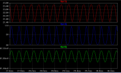
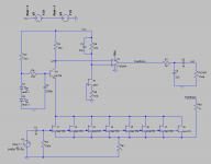
As for simple discrete, which I was still hoping for, I built the attached circuit last night. Without feedback the first and second stage behave almost identical to the simulation. But as soon as the third stage and feedback are attached, I get these square steps up to the rails. I don't really understand why; the simulation shows a good phase margin of more than 80 degrees.
In practice it's very hard to stabilize a three stage amplifier. You don't need much unmodeled phase to make it sing. By fully bypassing both emitter resistors you are making it worse.
Quick question: In the last circuit posted is feedback taken from Q3's collector or it is just an error in the schematic?
It is intended to be so, nevertheless, could be the wrong way to do it.
In practice it's very hard to stabilize a three stage amplifier. You don't need much unmodeled phase to make it sing. By fully bypassing both emitter resistors you are making it worse.
Any hints on how I might be able to fix it, besides removing the third stage? I know these are trivial issues for you the advanced ones, so it's ok if you don't have in interest in continuing the discussion about it.
8x 2SK170V??? And then a loop? Is it really controllable? See if it works with just 4 first.
P.S. Also a compensation cap over R6?
P.S. Also a compensation cap over R6?
Any hints on how I might be able to fix it, besides removing the third stage? I know these are trivial issues for you the advanced ones, so it's ok if you don't have in interest in continuing the discussion about it.
The DC gain of 1000 does not help either. This thing will have a very unstable operating point. If you just want to get it stable try setting up Q3 for AC gain of -1.
It is intended to be so, nevertheless, could be the wrong way to do it.
Yes, it seems that there is some positive feedback...
Have a look at this one, might give you some good ideas: http://www3.telus.net/chemelec/Projects/Preamp/Preamp-1.png
...anyway it gave me a new signature🙂
Last edited:
Quick question: In the last circuit posted is feedback taken from Q3's collector or it is just an error in the schematic?
If you just want to get it stable try setting up Q3 for AC gain of -1.
I agree with sidiy.
IMHO It seems there is a (overall) positive feedback.
If you just want to get it stable try setting up Q3 for AC gain of +1.(feeedbak taken from Q3 emitter)
Hmm... I assumed you had the sense of the feedback correct. Sometimes Spice does not care for DC convergence, it just finds the (un)stable point.
Wait a minute guys. I really did think that I applied negative feedback. The signal at the drain of jfets at a11 is inverted, then it gets inverted again in the second stage, so that the signal at a12 is now in phase with the signal at the source of jfets. Then it gets inverted again in stage three, so that at a13 we have a signal out of phase with that at the source of the jfets. Am I confused here?
Salas, I don't think the problem is the number of jfets; syn08 has it working with eight bf862.
Salas, I don't think the problem is the number of jfets; syn08 has it working with eight bf862.
Attachments

Wait a minute guys. I really did think that I applied negative feedback. The signal at the drain of jfets at a11 is inverted, then it gets inverted again in the second stage, so that the signal at a12 is now in phase with the signal at the source of jfets. Then it gets inverted again in stage three, so that at a13 we have a signal out of phase with that at the source of the jfets. Am I confused here?
Salas, I don't think the problem is the number of jfets; syn08 has it working with eight bf862.
The gate of the fet is the *non inverting* (+) input of the amplifier
The source of the fet is the *inverting* (-) input of the amplifier
The output of the amplifier *must* be *in phase* (not inverted) with the + input in order to be routed to the inverted input (think your amp like an Op_Amp)
so that the signal at a12 is now in phase with the signal at the source of jfets
so that the signal at a12 is now in phase with the signal at the *GATE* of jfets
Last edited:
Alright, now I got syn08's circuit working. Except, that big capacitor used in the servo loop, from the 1k resistor to Vcc got the whole thing motorboating, so I took it out. I'm using eight k170v jfets, and an opa2132 (the only jfet input opamps I got left). With the 1k resistor feedback and 1R source resistor I was supposed to get 60dB overall gain. Turns out the gain is about 56dB. There goes my hope for accurate gain setting. 🙁
Wait a minute guys. I really did think that I applied negative feedback. The signal at the drain of jfets at a11 is inverted, then it gets inverted again in the second stage, so that the signal at a12 is now in phase with the signal at the source of jfets. Then it gets inverted again in stage three, so that at a13 we have a signal out of phase with that at the source of the jfets. Am I confused here?
Salas, I don't think the problem is the number of jfets; syn08 has it working with eight bf862.
Yes, but BF862s have 7 times less Ciss than Violet 2SK170 and he uses SMD beads on each gate.
Before thinking about the above, you got VRs polarity like input signal's when using common source, and you have 3 stages in total each one inverting at its output in your cct, right? Then you got subtraction at Rs when closing a loop. Looks like NFB.
If 56dB is fixed, but is not achieving 60dB, it is still fixed so you can calculate the original input noise dividing the output noise by any steady gain. Maybe you can fix it at another lower number as well.
To make it simple: try to see node a10 as comparing currents contributed by the JFet's on one hand and the feedback resistor (R6) on the other hand.... though diy_audio_fo example is even better 
so that the signal at a12 is now in phase with the signal at the *GATE* of jfets
Yes, the gate and source of the jfets are in phase.
Yes, the gate and source of the jfets are in phase.
Not if you consider them as inputs
If you enter the gate the drain signal is inverted
If you enter the source the drain signal is not inverted
Try you spice simulation
Why not use the 2 channel scope, he has the cct on test. Can see the polarity on source resistor side to side with the loop's take off point while not closed yet.
Turns out the gain is about 56 dB.
If this is true then it would indicate that the amplifier is working with near-zero loop gain. At which frequency did you measure? How did you measure? Have you verified that your measurement procedure is sound?
What's the collector-emitter voltage of Q5 (referring to the original schematic by syn08)? If that's well above 2 V or so you could increase R13 to get more loop gain. Also I suggest to remove R9.
Any hints on how I might be able to fix it, besides removing the third stage? I know these are trivial issues for you the advanced ones.
As Scott pointed out: no, designing a working three-stage amplifier is not trivial. There are suitable topologies but unless there is a reason for using them (I see none here) its better to just go with a two-stage architecture.
Samuel
OK guys, with the feedback, you were correct and I worked it out for myself until I got convinced.
Samuel, the measurement was made with the oscilloscope looking at the two channels and comparing. The sine generator was set to 1.5mV RMS, 1kHz. However, I then measured it on a Fluke 8920A and the numbers were quite a bit different. This reported about 59.5dB which is very close to the 59.6dB that the simulator got.
The thing is, the whole servo loop is useless because of my intention to use batteries and to refer the input to Vee, as I showed before, so that the jfets could enjoy a full 24V. So I decided to pull out the servo loop and instead bias the +IN pin of the opamp the way you do in your preamp. Have a look at the attached circuit. These are the simulator values, but in real life I used R6=2k, and Q1 = 2SC2911. At first I used for R6 a 5k trimpot and dialed in the right value by looking at the scope output.
For the feeback resistors Rf2 and Rf1 I used 1% parts, which I double checked on a GenRad 1657 RLC bridge to make sure the ratio is as close to 1000 as possible.
To test it I built another 1000:1 attenuator using the same resistor types as the feedback resistors. Then measured the input and the output attenuated on the Fluke 8920A. Double checked the values with a Fluke 931B differential voltmeter. Got a gain of 946, which is about 59.518dB.
At this point either my measurements are wrong, or the circuit somehow doesn't match the theory in some way. The last measurement I did on the HP 3585A spectrum analyzer, and measure the main harmonic, this time on 2kHz. The result was 60.15dB.
None of these instruments have been calibrated in a while, so there we go. I should probably use a 100R trimpot in series with Rf2 and dial in the gain as close to 60dB as I can measure, and call it a day? I was hoping that I could get the theoretical Rf2/Rf1 using stable precision resistors, so that I don't have to rely on my non-calibrated instruments.
Attachments
Have you tryed to put the 2200uF to the PSU and not to ground ?
Do you mean to Vcc?
- Home
- Amplifiers
- Solid State
- Simple 60dB discrete low noise amplifier (lna)