100 % right . I will have a drink on Thursday with John . I think Carlsbor was his favourite fairground amp . He has repaired everything I have ever named , uses Turbo Sound himself . As you say about makes and quality .
HH proves that something that others would dismiss have successful commersial lives . When I see amps that are 70% protection systems I despair . It is possible to build things that are simple and work .
HH proves that something that others would dismiss have successful commersial lives . When I see amps that are 70% protection systems I despair . It is possible to build things that are simple and work .
Last edited:
980W@2R 0.169%THD@20kHz
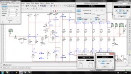
With just 24mA bias per device, and 9.3nV DC offset. 980W@2R ultra low THD of 0.169% @ 20kHz, with 5 pairs MJL21193/4. THD could be further reduced using more output pairs.
Just simulated my design, wonder it would perform like this in real.😉
Regards,
Aniket
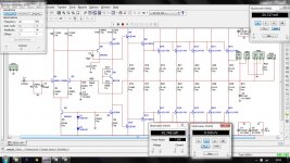
Here is a circuit of 2n3773 8 pairs,70-0-70 volt d.c. 42 volt output at 0.497% distortion power output 887 watts into 2 ohm
With just 24mA bias per device, and 9.3nV DC offset. 980W@2R ultra low THD of 0.169% @ 20kHz, with 5 pairs MJL21193/4. THD could be further reduced using more output pairs.
Just simulated my design, wonder it would perform like this in real.😉
Regards,
Aniket
Attachments
I think you could build it with a pair of devices and try 8R . How is it at 100 W 8 R ?
24 ma should be excellent as bias .
I often still use TO3 devices . I have no problem using flying wires to the PCB . That way adding a few is not difficult .
I have even run transistors in buckets of water . It sometimes works well enough until the water contaminates . 1 bucket per device . I think I have gone to 70V before now ?
My dream is to put some TO3's with their heads in a water pipe . It should work reasonably well . Not perfect as the die is on the connection side . A pump will be needed . Isolated TO3P even better . 90% could be in the water .
Why, of course not.Just simulated my design, wonder it would perform like this in real.
There's a ton of important parameters that simulation is not considering which will affect end results big way.
1.079 and 1.08 equals 2.159mA through Q3 collector. Add on ~1% of this for base current and you should have ~2.18mA through R6, giving Vr6=479.6mVdc.
Is that what is being modeled?
You MUST check this when you build !!!!!!!!!!!!!!!!
Is that what is being modeled?
You MUST check this when you build !!!!!!!!!!!!!!!!
It is a very brave design . I know of a commersial design that uses 0R47 as emitter resistors , the designer feels it gives reliability ( I have no idea if true , seems logical ) . He also insists only Motorola devices to be trustworthy . His belief is they survive double the current of competitors . His preference is for devices that offer 4 MHz . Again as they seem to be tougher and sound nicer ! No simulator knows that . Worth a thought ?
Even if you had no proper heat-sink you could run it for a few seconds with two output devices into an 8 ohm load . 2 x 50 watt car bulbs in series taken to 20 V rms would be a start ( careful they will get very hot , 4 = full load ) . If the amp doesn't die quickly you head for the sky . I feel a bit jealous of you , I am useless with simulators and yes I never read instruction manuals . Nelson Pass said the same . Hey what does he know ?
Even if you had no proper heat-sink you could run it for a few seconds with two output devices into an 8 ohm load . 2 x 50 watt car bulbs in series taken to 20 V rms would be a start ( careful they will get very hot , 4 = full load ) . If the amp doesn't die quickly you head for the sky . I feel a bit jealous of you , I am useless with simulators and yes I never read instruction manuals . Nelson Pass said the same . Hey what does he know ?
Actually, emitter resistors could be taken as a form of local feedback, so increasing their value will be good if they should run into a very difficult load.
As ever, there is a price to pay. Increasing their value can (but not necessarily) increase distortion and reduce bias to ridiculously low values. Off hand, the bias spread they are supposed to perform would be 30-40 mA per trannie, which is low.
Actually, Nigel, I've seen as much as 0.68 Ohms in commercial designs, Krell once did all of 1 Ohm, and the LAS I introduced in the other thread uses 1.5 Ohms, 17W emitter resistors, but admittedly, that's a rather exotic design.
The higher the value of the emitter resistor, and if the requirements stay the same, the higher power dissipation will be needed, although this also depends on what is expeczed of the amp regarding low impedances.
The point being that these resistors have much to do with thermal stability of the amp its so called "bias spread" under higher power dissipations.
In purely audio terms, the lower the value, the smaller their influence on the sound and the greater the transistors' ability to push out more current.
With all respect, Andrew, I would suggest you look over, preferably read in detail, Bob Cordell's manual on designing power amp. It's like 600 pages and is by far the most complete "manual" I have ever seen, compared to which Douglas Self is a baby in nappies.
You will find in it literally ALL of the procedures you need to follow, plus the math.
Last edited by a moderator:
Hi Dvv . Thank you for coming in as this gentleman seems to be ready to go on this . I think I might even go to 1R emitter resistors as they are cheap and a good place to start ( 1 W 3 W , 7 or 10 W preferably ) . Douglas Self thinks 0R1 OK and says crossover distortion will be marginally better . I have built with 0R1 and had no problems , just makes me very uneasy to go that low especially with the currents that might flow here . Although a horrible idea did anyone ever use halogen bulbs as emitter resistors ? Might just work as a crude but effective current limiter ? My guess is the feedback loop would clean them up . Outside a loop I have used them . They sound horrible . Some speakers use them ( ones that sound OK !!!! ) . I just crudely measured a 12 V 50 W type and got about 0R3 cold ( subtracting meter and prod readings ) . They would be 3R hot and after that a fuse . If we believe in negative feedback they might be inaudible ? Rotel claimed to be able to hear fuses in circuit . They also claimed feedback made them inaudible . I believe them espeically if Stan Curtis says so . Just think , if you rent out the amp and you put the halogens on the outside no one can say they didn't know the amp was clipping .
I should point out Mr Dvv has made commersial and advanced versions of amps like these for years . I always say he does very simple complexity and me very complex simplicity . This amplifier caught my attention because it seems to be neither . Doubtless it is a bit ambitious , where's the harm in that ? Doubtless it might not work perfectly first time ? . Myself I am always happy if it doesn't catch fire first time , even better if it respects my speakers .
I should point out Mr Dvv has made commersial and advanced versions of amps like these for years . I always say he does very simple complexity and me very complex simplicity . This amplifier caught my attention because it seems to be neither . Doubtless it is a bit ambitious , where's the harm in that ? Doubtless it might not work perfectly first time ? . Myself I am always happy if it doesn't catch fire first time , even better if it respects my speakers .
BTW . I just signed of Issues 2 of a PCB I am designing ( I should say doing it now ) . The boss had a slight change of direction and some parts look increasingly hard to get . We went from 1/8 watt to 1/4 watt resistors . I had used 1/8 watt in the past to help the building team differentiate the important parts ( some in other areas 0.1 % ) . I looked at surface mount which we sometimes use . A strange fact emerged . The military still prefers conventional and 1 /4 watt should continue . We only will make these in small numbers so prefer conventional . If the subcontractor is to capacity even me and the boss will make them !! If SMD no way ( I can , I don't , sometimes they are easier and solder nicely , the boss assumes we can't do it and I will not say otherwise , I have Parkinson's , get this I can not easily write a letter , I can solder SMD if I try , weird ) .
Asking the PCB company if 2 prototypes is OK these days he said 1 or 2 is becoming common . In the past they usually got to issue G when it started to work ! As much a I deplore simulation I am glade to do it in 1 or 2 . The PCB design tools often spot errors in my designs . Not serious ones , mostly just suggesting I can do better especially when at 100's of volts . I had one on this PCB . I hadn't said 25 V rms and the default value was 300 V . The PCB tools said a possible problem . I was so happy to think I had 1000 % on that one .
Asking the PCB company if 2 prototypes is OK these days he said 1 or 2 is becoming common . In the past they usually got to issue G when it started to work ! As much a I deplore simulation I am glade to do it in 1 or 2 . The PCB design tools often spot errors in my designs . Not serious ones , mostly just suggesting I can do better especially when at 100's of volts . I had one on this PCB . I hadn't said 25 V rms and the default value was 300 V . The PCB tools said a possible problem . I was so happy to think I had 1000 % on that one .
Cool down guys,
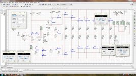
It's just an idea and my reply to Mr. Vedmitraa that even more power and lower THD values could be achieved for low impedance loads in simulation at least.
I am NOT at all intended to make this 980W amp. what for such an outrageous amount of power for home use.
However, I am currently working and tweaking this http://www.diyaudio.com/forums/solid-state/228463-anybody-know-amp.html
amp. for my home system and I expect around 250-300W@4R to power my speakers which are rated at 400W. A pioneer 12" sub(TSW1208D2) and an audiopro tweeter rated at 50W using a passive crossover.
Regards,
Aniket
http://www.diyaudio.com/forums/solid-state/228463-anybody-know-amp.html
Attachments
FWIW, I liked aniket's design, my amps are usually as simple as that one and I know well what they can and what they can not achieve.
That's why I also commented (based on experience) that a copper-and-silicon real life one would perform much less than the simulation.
The *main* problem is that the simulator works with the parameters set by the designer , it does not know better.
There is written "+/*70V rails"? ... ok, so be it. (It thinks).
But such an amp, fed from a transformer/bridge/capacitors will see anything but "clean 70V" .
Current will travel through real copper wire, probably through connectors (unless it's hard soldered to the speaker 😉 ), etc.
All of which are at least resistive.
But the main culprit will be the PSU: will drop a lot, show ripple 40dB higher than the vanishing distortion, said voltage will be "modulated" by current consumption, etc.
In fact that amplifier will need quite a good transformer to supply more than 600W RMS into a 2 ohms load.
Definitely less than 700W.
It also shows no short protection, which in a few applications might not matter much (hardwired fixed PA or Club systems) but in any portable system (PA/DJ) are most important.
But the worst is that at such high power levels heat dissipation is crucial, so it pays to go to use at least Class F/G/H types.
A Class AB amp, around 70% efficient, will have to dissipate that extra 30% as pure heat.
300W of heat are a *very* serious problem.
Not forgetting the the power transformer will also have its share of heat to dissipate too.
Nobody told the simulator that 🙁
Also; please do not be cheated by the fake *sensation of precision" simulators give.
That their Math is set to provide 5 significant digits or more, only reflects what the software writer thought approppriate, but end results can't be more precise than the data we feed it.
If I measure , say, 27.1V across a nominal 8 ohms load, my calculator will provide "impressive precision" 3.3875 A current ... which hides the fact that my voltmeter could provide either 27.0 , 27.1 and 27.2V and can't show a finer resolution
Yet a power calculation with such results would yield:
V^2 / R=734.41/8=91.80125 W
Impressive "precision", huh?
Of course, such amp should be rated "90W" or even "92W", although that final display of precision might be challenged on at least a few units out of the production line, simply because of normal parts tolerance.
I think someone should build this amp . If no one does I will one day . I gave my halogen bulb protection idea some thought . If used with 0R47 it looks to me to satisfy the original design aims .That is 0R47 and 0R3 ( bulb ) in parallel . This can be taken down to 0R33 and halogen bulb . In fact one might even try 0R22 and the bulb . The big deal is as current rises the bulbs resistance increases . This mimics how an audio FET would react . The trick is to get the right compromise . The bulb alone would rise to 3 R at only 4 amps . That is not unlike an FET , however that is a bit drastic . Most FET's are 1R at 100 mA already . Additionally 4 amps would be the limit . One could use two bulbs . The reason not to is the nature of the resistance curve .
@JMFahey
I took your message as a reminder that we should not look at the result and move on, rather that we should try to correlate that result with other aspects of the same problem.
I am using a simulator which has, during the last 7 or 8 years, never once failed me. If it says something will work, that something has never yet failed to work. If anything, the simulator is a little conservative, because the and result with a live circuit will always do BETTER than the simulator says it will. For example, the sim says it'll do say 300 kHz, and I find it does 360 kHz under the same conditions.
But your point is a fair one. An astonishingly large number of people using simulators never even consider to investigate the default values, and thus end up using "perfect" parts. My first job with it was to set the default values in the real world doman, so my capacitors are all rated at +/- 20%, my resistors at 1% metal film (because that's what I use by default), but I never forget to change that to say 5% for metal oxyde emitter resistors, and my nominal load is 8 Ohms +/-10%.
When I need a garden variety op amp, I am given a choice of several SPICE definitions (e.g. National Semiconductor, ITT, Analog Devices, Burr-Brown, and some have several SPICE version for submodels, say Nat Semi version N).
The point is, the sim cannot give you better results than your input data allows for. The more precise your input data, the more certain the sim results. Sure, it's a pain and a hassle, but that's what precision demands.
If your sim allows it, you may also want to create your own SPICE models based on manufacturer's Data Sheet. Sometimes, the SPICE definitions of some parts are unrealistically set, made almost perfect, when in fact we all know they differ from one manufacturer to another.
Just my 2 cents' worth.
Marantz used 6.3V/4A bulbs as emitter resistors in the Model 14/15 power amplifiers. They did not light up until you drove it very hard at 4Ω (clipping). That bulb would be about 1R575 at 4A, and about 0R07 cold.
@Aniket
If I may, I'd like to suggest some alternative views and possibilities.
For a start, I think you need to seriously review your concept of "simple". No doubt the KISS ("Keep It Simple, Stupid") principle has merit, time and experience have proved it.
HOWEVER, I think you took it too literally at its face value, and started out by literally trying to use as few parts as possible. I feel this is wrong. You should understand it in a more flexible manner, use as few as possible FOR A GIVEN DESIGN GOAL, not absolutely.
Look at just two things. First, how much power do you want under which circustances? If you go for the holy grail of power amps, i.e. to make it an ideal VOLTAGE source, you would want 20 Vrms into 8 and down to 2 Ohms, say, but that means you need as much as 14 Amps of current. Think of the heat produced by such a power stage.
This begs the question - 200W/2 Ohms HOW? On a continuous basis, this would likely mean that the heat generated would at some point trigger thermal protection. Also, continuous mode is a laboratory measure, in real life you always need to leave some headroom if you don't want serious clipping to happen to you (and believe me, you really don't!). This means your amp should be good for a stable CONTINUOUS power delivery of say 10-20 WRMS, and the peaks it should be able to ride out on its capacitors.
Not to elaborate further, you get the idea - you need to PLAN for it all, and thus design for it all.
A second matter might be that you should know, in general terms, how you want your circuit to operate. Do you want no local degeneration and put all your trust in global NFB, or do you want local degeneration, dealing with distortion in the places it occurs in, and thus will need muh less global NFB?
For example, the current generator you use is the worst type regarding CMRR, but it's the simplest and heapest around, and will work without fail. I'll wager that if you changed it for a better one, you would gain in amplifier resolution because that gerenator is outside the NFB loop, so there's no correction for mistakes made.
So, sit down and think about what you want starting backwards - begin with the output stage and its own issues. Forget simplicity as a goal, that's art for art's sake, but do think of it when the amp start to take some tangible shape.
Marantz used 6.3V/4A bulbs as emitter resistors in the Model 14/15 power amplifiers. They did not light up until you drove it very hard at 4Ω (clipping). That bulb would be about 1R575 at 4A, and about 0R07 cold.
I like this idea . The halogens are cheap , plentiful and tough . It is a shame , I just repaired a Rotel amp . It is fused at 4A and the transistors always seem to survive a blown fuse , thus no great risk to try to the full . The fuse is in the feedback loop . It would have been ideal as a basic test . OK , not the emitters . One step closer to the speakers . Good enough for a listening test of feedback and a horrible resistor .
The point is if someone has a 1000 W amp you can be sure someone will clip it . Most PA manufacturers know this , accept it and design with this in mind .
I have a 1000 VA 55 - 0 - 55 . It looks tempting to have a go . I also have a massive heat-sink with numerous TO3 holes ( perhaps 10 ? ) . A gift from a friend . I have a bunch of 4700 uf 100 V .
With just 24mA bias per device, and 9.3nV DC offset. 980W@2R ultra low THD of 0.169% @ 20kHz, with 5 pairs MJL21193/4. THD could be further reduced using more output pairs.
Just simulated my design, wonder it would perform like this in real.😉
Regards,
Aniket
o.1 Ohm 5W 1% emitter resistors? Never seen anything like that. The best I know of are 5% metal oxyde 5 and more Watts emitter resistors.
At 24 mA bias (if I got it right), and 0.1 Ohm, your amp is severely underbiased; to be properly biased, it should have at least 240 mA per transistor with 0.1 Ohms.
Because it is severely underbiased, it will probably sound slow and heavy, and will have problems at high power levels because of very bad bias spread.
On the plus side, in comparison with your initial 50W amp project, you have come a long way in a short time. This topology is light years ahead of the original one, but is still just a good beginnig. Don't worry, we've all been there and have moved on since, some things simply need time.
As you have been told by others, you would do well to put in a 47-100 Ohm resistor in series with your driver transistor base, and 2.2-12 Ohms in series with your power stage transistor.
They serve to reduce chances of oscillations appearing, which can happen at sometimes surprisingly high frequencies for a bipolar power device. I assume this is what Nige's brother referred to.
One observation - NOBODY here seems to produce the usual prudent protection against overheating, overcurrent, overvoltage and excessive DC in output signal. Any of these could easily take out the amp, the speaker or both. Also, no elimination of capacitors by using DC Servo circuits, which are essentially rather simple. No matter which, from no matter whom, at no matter what price capacitor is always inferior to the capacitor which is not there.
On this amp in specific - it will possibly deliver 980W/2 Ohms in short peaks only (which is realistically all you would ever need). Look up the data sheet and do the derating as shown there assuming only that it had been working at 1/10 of nominal power beforehand, meaning that it had reached something near to its normal operating temperature. Remember we usually keep heat sink cutoff temperature at 65 deg C, which means that our junction temperature is at least 85 deg C. Derate as shown and you will see we can't really expect much more than 550-600 WRMS into 2 Ohms on any sustained basis because of overheating.
Also, you can reduce its VAS current from 10 mA or so to 5 mA, that's more than enough given that you have a triple output stage topology (predriver, driver, power). That in turn allows you to use BF 721 instead of the MJE transistor, thus reducing your inherent distorion from nominal 0.169% to less than 0.08% or less.
- Status
- Not open for further replies.
- Home
- Amplifiers
- Solid State
- Simple 100W power amp