Where to begin?
First off, I would split the power supply lines for the VAS from those for the output stages. This is more involved and costlier, but offers many advantages, the key one being that you can increase the voltages for the VAS without unduly stressing the output stage and its SOAR. It would make your imaging rock steady under all conditions even beyond output stage clipping (God forbid!).
Without doing any calc, I assume you opted for a high level of global NFB. I would go the other way, more local and less global NFB, but it is what it is.
In that light, I would suggest you use a cascode for the VAS, given its many advantages over the classic Darlington stage you did use. The key advantage being that you can make it with a settling time (the far too much overlooked apsect) shorter by a factor of 10:1 in comparison with a regular cascode stage.
The MJE 340/350 tranistors could be easily replaced by much better, yet still econoically viable transistors. You are using a triple output stage, which means it has a very high current gain factor, and in trn this offloads the VAS stage in terms of required drive current, from say 10 mA to say 5 mA. At 5-6 mA, I doubt you'll find a more linear device than BF 720/721, their only cabeat being that they are SMD parts, so soldering them is a bit tricky, you need to be careful and have a fine tipped soldering iron, but that's all.
Due to their unusually wide bandwidth for that class of transistors, quoted as over 100 MHz, and their execution, simply installing them will decrease your inherent THD by quite a bit and very possibly widen the open loop bandwidth quite a bit too.
Your base resistors on your output transistors is too low, 1 Ohm is really low. I would go for AT LEAST 2.2 Ohms, or much more probably 4.7 Ohms.
Your emitter resistors of 0.1 Ohms is also far too low, I think, unless you plan on quiescent current running though the output trannies to be 200 mA and more. Remember, they are there primarily as bias spreaders, and at 0.1 Ohms you have to have a lot of current to be spread. That would mean that each transistor was working up to (56 * 0,2) 12W in pure class A, or (8 * 12) 96W of pure class A dissipation. Good for the sound, bad for the power bill and the required heat sink area and type.
I note you have used a fixed bias. Personally, I would never do that, because in time, you will have to readjust it.
I may have missed it, but I don't recall any method of adjusting for zero DC at the output. Again, you will have to readjust in time.
Last but not least, I saw no protection circuits for overheating, excess DC at the output, overvoltage and overcurrent. I know they have a bad reputation for interfearing with sound, but this is a half truth - they are bad when you design them poorly, or when you are pushing an output stage to go where it shouldn't. If you're willing to consider tham, I could help you out.
You may think I am nitpicking here, but having seen a few worthy efforts go up in smoke because "protection circuits ruin the sound", I tend to be cautious. In most of my works, the protection ciruits never triggered at all, but were there nevertheless, just in case. Yout typical fuse, often used as the sole means of protection, can take up to 5 seconds to blow, whereas a power transistor could burn out in less than 1 second. Which is why I have seen quite a few commercial amps with burnt out power sections and complete and functional fuses.
Don't run, don't rush, think of it before you make any decisions.
Throw away the MJE340/350s
Select transistors that suit VAS duty and pre-driver duty.
Agreed, While tey will work, they are really quite outdated and a number of better devices exist at the same cost.
2n5551 are not good for the input LTP. ...
Really? And why not, Andrew?
Where to begin?
First off, I would split the power supply lines for the VAS from those for the output stages. This is more involved and costlier, but offers many advantages, the key one being that you can increase the voltages for the VAS without unduly stressing the output stage and its SOAR. It would make your imaging rock steady under all conditions even beyond output stage clipping (God forbid!).
Without doing any calc, I assume you opted for a high level of global NFB. I would go the other way, more local and less global NFB, but it is what it is.
In that light, I would suggest you use a cascode for the VAS, given its many advantages over the classic Darlington stage you did use. The key advantage being that you can make it with a settling time (the far too much overlooked apsect) shorter by a factor of 10:1 in comparison with a regular cascode stage.
The MJE 340/350 tranistors could be easily replaced by much better, yet still econoically viable transistors. You are using a triple output stage, which means it has a very high current gain factor, and in trn this offloads the VAS stage in terms of required drive current, from say 10 mA to say 5 mA. At 5-6 mA, I doubt you'll find a more linear device than BF 720/721, their only cabeat being that they are SMD parts, so soldering them is a bit tricky, you need to be careful and have a fine tipped soldering iron, but that's all.
Due to their unusually wide bandwidth for that class of transistors, quoted as over 100 MHz, and their execution, simply installing them will decrease your inherent THD by quite a bit and very possibly widen the open loop bandwidth quite a bit too.
Your base resistors on your output transistors is too low, 1 Ohm is really low. I would go for AT LEAST 2.2 Ohms, or much more probably 4.7 Ohms.
Your emitter resistors of 0.1 Ohms is also far too low, I think, unless you plan on quiescent current running though the output trannies to be 200 mA and more. Remember, they are there primarily as bias spreaders, and at 0.1 Ohms you have to have a lot of current to be spread. That would mean that each transistor was working up to (56 * 0,2) 12W in pure class A, or (8 * 12) 96W of pure class A dissipation. Good for the sound, bad for the power bill and the required heat sink area and type.
I note you have used a fixed bias. Personally, I would never do that, because in time, you will have to readjust it.
I may have missed it, but I don't recall any method of adjusting for zero DC at the output. Again, you will have to readjust in time.
Last but not least, I saw no protection circuits for overheating, excess DC at the output, overvoltage and overcurrent. I know they have a bad reputation for interfearing with sound, but this is a half truth - they are bad when you design them poorly, or when you are pushing an output stage to go where it shouldn't. If you're willing to consider tham, I could help you out.
You may think I am nitpicking here, but having seen a few worthy efforts go up in smoke because "protection circuits ruin the sound", I tend to be cautious. In most of my works, the protection ciruits never triggered at all, but were there nevertheless, just in case. Yout typical fuse, often used as the sole means of protection, can take up to 5 seconds to blow, whereas a power transistor could burn out in less than 1 second. Which is why I have seen quite a few commercial amps with burnt out power sections and complete and functional fuses.
Don't run, don't rush, think of it before you make any decisions.
now ...what can you say to this guy ...ABSOLUTELY NOTHING EXCEPT +1000
now ...what can you say to this guy ...ABSOLUTELY NOTHING EXCEPT +1000
Just say КАЛИМЕРА, that's quite enough. 😛
Wouldn't complain if you put forth some Mythos and tzatziki, trust me. 😀
These guys have interesting transistors . The say 10 MHz for MJE 340/350 , some say 6 MHz and others 30 MHz ( Philips of old ? ) . They also have input stage transistors .
Medium Power-Driver
I often use non polar electrolytic as a protection device during the proving period of an amplifier . Although a crude method it is often is far more transparent than many would think . 4000 uF at 16 V is OK for testing the most critical watts ( 0 to 5 watts ) . This is often overlooked with big amplifiers . It would be like a motorcar that is only pleasant on the motorway . Around town matters greatly ( 0 to 5 watts ) .
The Quad 405 protector would be worth a thought . Can always be switched out for home use .
http://www.diyaudio.com/forums/solid-state/5083-triacs-used-crowbar.html
I have always suspected DC offset a good thing up to 100 mV . I wonder if zero DC offset and zero distortion are like drinking water made from the elements . Seemingly ideal , unsellable as bottled water . Accepting we might have either error is it not wise to ask if a friend or enemy ?
I suspect many speakers would have lower distortion if deliberate DC offset was used . This would help compensate for nonlinear magnetic field at high volume . It could be variable and signal activated .
ΚΑΛΗΜΕΡΑ THEN
shipping address please😀
Thank you, Sakis, but really, no need. I live right across the street from a very large Vero supermarket, where I can buy Mythos (excellent Greek beer) and most of what there is from Greece in exports any day of the week.
As you probably know, we Serbs derive our language, customs and religion from Greece, so reading Greek isn't a problem for me (and while I can read it, I don't necessarily know what it means).
And guess where my family and myself spend our summer holidays every summer from 1990? 😛
Trust me, I know every hole in every road from Thessaloniki to Cassandra. Like every good criminal, I tend to return to the scene of the crime as often as I can. 😀
But seriously, I have been returning to Greece ever since February 1964, when I visited it for the first time, as a kid of 11. If I was not Serbian, I would want to be Greek.
But that's off topic, so let's leave it at that.
Last edited:
The first time I decided to build a amplifier from scratch, I asked this forum for help.
At first the input I got made me feel like they were just picking on my design,
I took some of their advice but not all,
Well after building the amp, it worked, but I still wanted something better,
So I went back and took more of the advice from the forum members,
In all I changed the design 5 times each time redesigning the pcb and building it.
I must say I learned a lot from all of that.
But thinking back I should have spent more time in the design of the amp right at the start
In this way getting something I would really be proud of, then only minor tweaks will need to be made after your first build.
I guess what I'm saying is don't rush, listen to the forum members, they are really a great help.
It's more rewarding building a great amp, than one that only works ok.
Regards
Nige, MJE 340/350 were initially developed for TV sets and were never meant to be used in audio. Which does not mean you must not use them, but if you do, be prepared to pay the price.
As you know, I would always recommend the BF series. Not one of them goes below 60 MHz and many are 250V+ rated, so no Early effect under any reasonable conditions.
In case of this amp, I have mixed feelings. If it's being made for home use, then plastic pack 2SC5200/2SA1943 tranistors are a good compromise between function and price. If it were being built for say studio use, I would recommend making use of Motorola/ON Semi's MLJ 3281/1302, since they have a rating of an extra 50W per transistor, and that is a significant power margin.
But if you're into thunder, lightning and brimstone, then I'd use four pairs of Motorola/ON Semi's MJ 21193/21194. Note just "MJ", metal TO-3 packaging, not "MJL" which is plastic TO-264 packaging; each is rated at 250W of power. Four pairs of these will simulate an earthquake very easily and very credibly.
@Vostro
Exactly right.
I reckon you should be spending at least one half the time in designing. The first thing one has to do is to work out what he wants that amp for and under which conditions will it perform as desired.
Usually, I advise people to go backwards - decide the operating conditions and work out the output stage first, knowing what it will face.
Then work out the topology you want to use - single ended input, fully complementary, simple differentials or cascodes, and so forth.
If you do so, the rest is easier and simpler to do, as you already have many answers to most questions.
And NEVER EVER mistake quantity of power with quality of sound. What you need is a reasonable balance between the two, and if you do err, always err on the side of quality.

dvv I have edited and removed two email addresses and accompanying text in earlier posts where you seemed to be offering files of Bob Cordells book.
Such practice is theft
Nige, MJE 340/350 were initially developed for TV sets and were never meant to be used in audio. Which does not mean you must not use them, but if you do, be prepared to pay the price.
As you know, I would always recommend the BF series. Not one of them goes below 60 MHz and many are 250V+ rated, so no Early effect under any reasonable conditions.
In case of this amp, I have mixed feelings. If it's being made for home use, then plastic pack 2SC5200/2SA1943 tranistors are a good compromise between function and price. If it were being built for say studio use, I would recommend making use of Motorola/ON Semi's MLJ 3281/1302, since they have a rating of an extra 50W per transistor, and that is a significant power margin.
But if you're into thunder, lightning and brimstone, then I'd use four pairs of Motorola/ON Semi's MJ 21193/21194. Note just "MJ", metal TO-3 packaging, not "MJL" which is plastic TO-264 packaging; each is rated at 250W of power. Four pairs of these will simulate an earthquake very easily and very credibly.
That was the point . I say 6 MHz . The link gives some ideas . I do note the designer wants to use devices from close to home .
I have used paralell MPSA 42 and 92 with great success , the emitter resistors chosen to spread the load . If the VAS is converted to a Cascode a high degree of magic occurs . High gain , high voltage , high linearity , low price and good high frequency response . Absolutely no problems when I tried it . Take Cdom to collector of upper transistor group and base of the high gain device . I suspect even the MJE340/350 will work better in a Cascode ( BC550/560 C perhaps ) ? Most transistors work better in common base if the circuit is OK driving it .
That's a good suggestion................ I suspect even the MJE340/350 will work better in a Cascode ( BC550/560 C perhaps ) ? Most transistors work better in common base if the circuit is OK driving it .
It is one of D.Self's recommendation, but he adopts the helper EF instead to save cost for his target audience.
I think the cascode is the better system for the VAS, but it must be followed by a high impedance load, there's the extra cost another EF is required.
Thanks all for valuable info.
Firstly,
regarding the mje's340/50, for VAS and predriver duties, they are easily obtainable, these are tested in VAS positions in The DIYAB amp(honey badger), Quasi's Nbip, Nmos series, Apex AX17, B500 and many other designs and they work, not that great, but they work and work in my simulation also. I would definitely use the recommended Transistors for VAS and predriver duties(BF720/21, BF469/70 or the excellent 2SC3503/KSC3503 and its complementary) but only if i could get them here. These are almost impossible to find here, even if I tour the whole India. 2SC4793 and 2SC5171 are easily available but they dont work well in VAS positions, in simulation atleast. Also BD139/140 could not be used for their limited Vceo of 80V. For the input stage i used 2n5551 as they see about 50V across C-E. So BC547 could not be used and the BC546 is on its edge. 2N5551/5401 are used in many other successful amps in the forum like DX blame mk3, Apex AX14,17 even Bob Cordell used these in his book for examples. I know there are other great devices specifically for the input stage, but again parts sourcing is an issue. Please mention any other good substitutes, most importantly obtainable.
Secondly,
regarding the bias, it was set at 35mA per device and that's why a fixed 464R was used, definitely a trimmer would be used in the working circuit to tune the bias. I have used 0.1R emitter resistors as i have a bunch of them, got 3.5mV across them to get 35mA bias current. I have even used them in my other working designs, no problem at all. The VAS current is 7.2mA, LTP is 1.5mA.
The base stopper resistors of output devices would be increased, to 2.2R. The incredible MJ21194/95 or MJL3281/4281 are also impossible to obtain genuine here. Those available are MJ15024 and NJW0281 but each single transistor of these cost thrice as much as a 2SC5200/1943 pair would. So i used 2SC5200, and 4 pairs of these at +/-56V supply, and 4 pairs could handle that i suppose, and they are cheap and easily available.
Thirdly,
regarding the DC offset, i got 0.00471V at the output in the simulation. For the sake of precaution i used BC546 as Q1 and 2N5551 as Q2 for the LTP, both different, the DC offset varied only +/-10mV. So no trouble here for the DC offset. If, there would be any in the working circuit, then R5 would be replaced by a trimmer, which in turn would change the LTP current if altered.
Splitting the power supply between VAS and output stage is way too complex for me.
Regarding the protection circuit, i would use a separate, DC protection, short circuit protect and soft start circuit, very good circuits are already in the forum by Apex and others also. So the protection circuits would be on a separate PCB.
I have seriously learned a lot in the forum, that's why I post here. I am in no hurry, but i just get excited with the simulation results, and prematurely plan to build the thing. I just believe to evolve the design. Also I have no experience in PCB designing, so anyone could please help me design the PCB for the final design.
Thanks all for your input.
Regards,
Aniket🙂
Also, this would be used as a full range amp. Why someone would need a 250W amp for mids and highs. Even a 20W amp would do in that place.😀
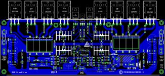
PCB rev 1.0
@Aniket just in time rev 1.0 of the amplifier ..... spend all day on layout PCB 🙂
Regards,
Alex.
@Aniket just in time rev 1.0 of the amplifier ..... spend all day on layout PCB 🙂
Regards,
Alex.
Attachments
Last edited:
dvv I have edited and removed two email addresses and accompanying text in earlier posts where you seemed to be offering files of Bob Cordells book.
Such practice is theft
If you already haven't, please look at your mailbox, there's a message from me regarding the matter.
For the record, having seen the body of text being offered free of charge on a number of sites, I was led to believe no copyrights regarding distribution applied.
It appears I was wrong.
I apologize for my mistake and assure one and all that will not happen again.

@Aniket
Regarding 2SC5200/2SA1943, please do not misunderstand me, they are a perfectly fine choice if the amp will not often be pushed to its limits for any longer period of time, or, alternatively, if you use a lot of heat sinking, really a lot ("really a lot" being say, 2*0,42 heat sinks per channel).
Professional studio requirements are more stringent, while live act requirements are yet more stringent.
So, the final choice is actually determined by what you want. For home use, even heavier heavier use, the ones you used are perfectly fine. To endanger them, you'd really have to run the amp at very high levels over a protracted period of time into some really evil loads, like the Apogees (they were nicknamed "The Amp Killers").
As for real vs fake transistors, rest assured, 2SC5200/2SA1943 are just as prone to fakes as any other popular device. It's problem of global proportions.
No comment on protection circuits?
@Aniket just in time rev 1.0 of the amplifier ..... spend all day on layout PCB 🙂
Regards,
Alex.
Alex, you wouldn't happen to be living somewhere in Romania near to the Serbian border, would you?
Your talent could become a source of income for you ...
- Status
- Not open for further replies.
- Home
- Amplifiers
- Solid State
- Simple 100W power amp