That sounds right. The supply will turn on when first connected to the control board and will remain on until the control board goes through it's first power up and shut down cycle.
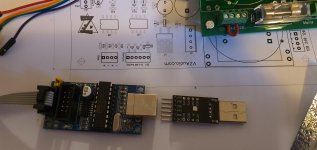
Hi Valery, is there any difference in the programing procedure from the guide if the board is allready fully populated? Once I connect to the J10 do I need any power to the board from the mains? Or its still as described in the guide? Also the 6 inline J9 header any special procedure to be used if the board is populated in full? I am using the two boards sugested by you guys previously.
Attachments
When the board is fully populated it's usually best to use the boards power supply to power everything while programming. To flash the bootloader usually there is a jumper that you remove from the USBTinyISP to disconnect it's 5V power, likely the yellow one on yours. When loading the actual software simply leave the 5V unhooked.
Hi, what if I cant disconnect the 5V with the jumper out? I will measure today and see if I take the jumper off the 5V is no longer present. Hopefully everything will go ok and get it done todaay.
Thanks,
Florin.
Thanks,
Florin.
If you can't disconnect the 5V line from the USBTinyISP the power supply on the control board would be directly connected to the 5V USB power on your computer, which could possibly damage the motherboard if it was poorly designed, but likely wouldn't hurt anything. I would try flashing the bootloader with the control board powered from the USBTinyISP in that case.
Hi Valery , how to use the Arduino uno board to burn the bootloader? I have one of those also. I have tried using the USB tiny board but it gives an error , that it cant connect to the USB tyni device, sometimes the ArduinoIDE software detect the bord , name, port... but when trying to burn the bootloadrr it shows that error. The cable I have installed the correct way, I have checked the pins and no issue. The control board wasnt powered just for you to know.
This is the error that I get: could not find usbtiny device (0x1781/0xc9f).
Thanks,
Florin
This is the error that I get: could not find usbtiny device (0x1781/0xc9f).
Thanks,
Florin
Hi just got back from trying to use the Uno board , its better but I get this error when I try to load the bootloader : Arduino: 1.8.12 (Windows 10), Board: "Arduino Uno"
avrdude: stk500_recv(): programmer is not responding
avrdude: stk500_getsync() attempt 1 of 10: not in sync: resp=0x03
avrdude: stk500_recv(): programmer is not responding
avrdude: stk500_getsync() attempt 2 of 10: not in sync: resp=0x03
avrdude: stk500_recv(): programmer is not responding
avrdude: stk500_getsync() attempt 3 of 10: not in sync: resp=0x03
avrdude: stk500_recv(): programmer is not responding
avrdude: stk500_getsync() attempt 4 of 10: not in sync: resp=0x03
avrdude: stk500_recv(): programmer is not responding
avrdude: stk500_getsync() attempt 5 of 10: not in sync: resp=0x03
avrdude: stk500_recv(): programmer is not responding
avrdude: stk500_getsync() attempt 6 of 10: not in sync: resp=0x03
avrdude: stk500_recv(): programmer is not responding
avrdude: stk500_getsync() attempt 7 of 10: not in sync: resp=0x03
avrdude: stk500_recv(): programmer is not responding
avrdude: stk500_getsync() attempt 8 of 10: not in sync: resp=0x03
avrdude: stk500_recv(): programmer is not responding
avrdude: stk500_getsync() attempt 9 of 10: not in sync: resp=0x03
avrdude: stk500_recv(): programmer is not responding
avrdude: stk500_getsync() attempt 10 of 10: not in sync: resp=0x03
Error while burning bootloader.
I have set Programmer : Arduino as ISP.
Is that right?
Thanks again,
Florin
avrdude: stk500_recv(): programmer is not responding
avrdude: stk500_getsync() attempt 1 of 10: not in sync: resp=0x03
avrdude: stk500_recv(): programmer is not responding
avrdude: stk500_getsync() attempt 2 of 10: not in sync: resp=0x03
avrdude: stk500_recv(): programmer is not responding
avrdude: stk500_getsync() attempt 3 of 10: not in sync: resp=0x03
avrdude: stk500_recv(): programmer is not responding
avrdude: stk500_getsync() attempt 4 of 10: not in sync: resp=0x03
avrdude: stk500_recv(): programmer is not responding
avrdude: stk500_getsync() attempt 5 of 10: not in sync: resp=0x03
avrdude: stk500_recv(): programmer is not responding
avrdude: stk500_getsync() attempt 6 of 10: not in sync: resp=0x03
avrdude: stk500_recv(): programmer is not responding
avrdude: stk500_getsync() attempt 7 of 10: not in sync: resp=0x03
avrdude: stk500_recv(): programmer is not responding
avrdude: stk500_getsync() attempt 8 of 10: not in sync: resp=0x03
avrdude: stk500_recv(): programmer is not responding
avrdude: stk500_getsync() attempt 9 of 10: not in sync: resp=0x03
avrdude: stk500_recv(): programmer is not responding
avrdude: stk500_getsync() attempt 10 of 10: not in sync: resp=0x03
Error while burning bootloader.
I have set Programmer : Arduino as ISP.
Is that right?
Thanks again,
Florin
Attachments
Last edited:
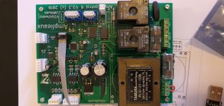
I usually get that error if there's something shorted on the board, but it could also be from not enough current being supplied from the programmer. Verify that you have 5V present on C9 and also on both sides of R10
Hi Valery , how to use the Arduino uno board to burn the bootloader? I have one of those also. I have tried using the USB tiny board but it gives an error , that it cant connect to the USB tyni device, sometimes the ArduinoIDE software detect the bord , name, port... but when trying to burn the bootloadrr it shows that error. The cable I have installed the correct way, I have checked the pins and no issue. The control board wasnt powered just for you to know.
This is the error that I get: could not find usbtiny device (0x1781/0xc9f).
Thanks,
Florin
This error usually means either the drivers aren't installed or USBYinyISP power supply is overloaded and it's shutting down.

Hi, there were no shorts on the control board , I clraned the board with alchool and no problemes of this kind, if I got that message I gues the bootloader is loaded. Now I need to try and load the I2C scanner sketch ( where can I get the one you guys used? ), also the small 6 pin adapter that I have, the one posted earler has a little different pinout designation than the one in the control boards schrmatic for J9.
Can you help me with some clarification before I start connecting it?
Thanks,
Florin
Can you help me with some clarification before I start connecting it?
Thanks,
Florin
Your board is fine if the boatloader installed successfully. To load the software you will need to connect the RXD pin of the CP2102 to RX on the control board, TXD to the TX pin, GND to ground and DTR to reset. You need to install the CP2102 drivers before your computer will recognize the CP2102.
Hi, thanks for replying, so there is no need to connect the CTS and RTS pin? These are available on the small adapter, but I would have to solder some pins to the sides, these are available for me but not where the connector (the 6 pin 90 degrees one) is allready soldered. So I just need the GND, RXD, TXD, and DTR, why is there reset pin availabke on the adapter ? Should I understand its the same as DTR ( DTR would be Data Reset?).
So just to confirm I need the I2C scanner(please sugest the one that works great, the one you guys used if you can), hook up the modules one by one to the board powered by the mains, get the addresses, put them into the sketch, after that save the sketch, upload using the same adapter and proceed after that as in the build guide?
Thanks,
Florin
Last edited:
The reset pin on the adapter is used to reset the adapter, this isn't what you want to happen. What needs to happen is the reset pin of the control board needs to be pulled low briefly putting it into program mode, then you write to it through the RX and TX lines. One of the features of the CP2102 is that it pulls it's DTR pin low briefly before transmitting serial data, so it works perfectly for this. The CTS and RTS pins behave a bit differently and don't work reliably.
Here's the I2C scanner sketch. A I2C Scanner for Arduino * GitHub. Yes just get all the addresses, edit the sketch and load it on.
Here's the I2C scanner sketch. A I2C Scanner for Arduino * GitHub. Yes just get all the addresses, edit the sketch and load it on.
Hi just got back from trying to use the Uno board , its better but I get this error when I try to load the bootloader : Arduino: 1.8.12 (Windows 10), Board: "Arduino Uno"
avrdude: stk500_recv(): programmer is not responding
avrdude: stk500_getsync() attempt 1 of 10: not in sync: resp=0x03
avrdude: stk500_recv(): programmer is not responding
avrdude: stk500_getsync() attempt 2 of 10: not in sync: resp=0x03
avrdude: stk500_recv(): programmer is not responding
avrdude: stk500_getsync() attempt 3 of 10: not in sync: resp=0x03
avrdude: stk500_recv(): programmer is not responding
avrdude: stk500_getsync() attempt 4 of 10: not in sync: resp=0x03
avrdude: stk500_recv(): programmer is not responding
avrdude: stk500_getsync() attempt 5 of 10: not in sync: resp=0x03
avrdude: stk500_recv(): programmer is not responding
avrdude: stk500_getsync() attempt 6 of 10: not in sync: resp=0x03
avrdude: stk500_recv(): programmer is not responding
avrdude: stk500_getsync() attempt 7 of 10: not in sync: resp=0x03
avrdude: stk500_recv(): programmer is not responding
avrdude: stk500_getsync() attempt 8 of 10: not in sync: resp=0x03
avrdude: stk500_recv(): programmer is not responding
avrdude: stk500_getsync() attempt 9 of 10: not in sync: resp=0x03
avrdude: stk500_recv(): programmer is not responding
avrdude: stk500_getsync() attempt 10 of 10: not in sync: resp=0x03
Error while burning bootloader.
I have set Programmer : Arduino as ISP.
Is that right?
Thanks again,
Florin
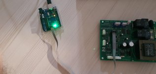
I figured out why this didn't work. Pin 10 of the Arduino used as the programmer needed to be connected to the reset pin on the control board. You had the reset pins for both boards connected together. The Control board wouldn't receive a reset putting it into program mode at the correct time this way.
Hi, does the CP2102 adapter must show on the programmer list in Arduino IDE to work? Because I have connected everything as you specified and it shows an error, should I switch RX to TX to work? The adapter shows up in the device manager list as the CP... , where would the issue be, any chance to use the Arduino UNO board to do this, does it has this ability?
Thanks,
Florin
Thanks,
Florin
The CP2102 should show up in the Arduino IDE as another com port when you plug it in. Is that happening?
You can pull the Atmega328 from it's socket on the Uno and jumper pin D0, D1, reset and ground to the control board.
You can pull the Atmega328 from it's socket on the Uno and jumper pin D0, D1, reset and ground to the control board.
Hi, If I choose the com6 port that shows the adapter connected i do get board info, no SN but It sees the adapter. Power to the Atmega on the cobtrol board I have so all is good there, I would assune all is ok in control board if I managed to get the bootloader written, I did it again just to check and It burned the bootloader just fine immediatly .
I will do some investigating and try again. Any more sugestion to get the board programmed?
Thanks,
Florin
I will do some investigating and try again. Any more sugestion to get the board programmed?
Thanks,
Florin
- Home
- Group Buys
- Simpelstark+ ODNF amplifier boards GB