Seems all within a SS range. Do you know current draw?
I have pinged Jens. Let's see how he feels about this.
Jan
I have pinged Jens. Let's see how he feels about this.
Jan
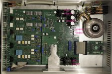
Not per regulator, only the three currents at the transformer output. They are all about 300mA during normal operation.
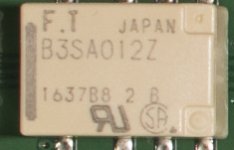
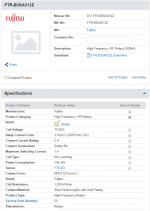
I assume the 12V is for the relays and I have not measured the current while relay switching.
I assume the 12V is for the relays and I have not measured the current while relay switching.
OK, thanks. Definitely SilentSwitcher land ;-)
The relay, if it uses the +12, will happily run on the +15 too. Remaining +5 and +6 can be another SS. I wonder what that +6 is used for?
Jan
The relay, if it uses the +12, will happily run on the +15 too. Remaining +5 and +6 can be another SS. I wonder what that +6 is used for?
Jan
There are no provisions for that. Two SilentSwitchers will have minute small output voltage differences, and if you parallel them the one that is slightly lower would start to draw current from the one that's slightly higher. So that won't work, sorry.
Can't you use the two SS's to supply two units, like two channels on a preamp?
Jan
When using multiple SS's does each need to have a separate supply from the wall?
Last edited:
When using multiple SS's does each need to have a separate supply from the wall?
No, you can supply both from the same USB source (or USB charger) or a wall-wart type supply, up to 12V max.
A SS can supply about 8-10W total, depending on voltage, which means that the max input requirement can be above 10W. Most standard USB chargers supply about 2A at 5V which nicely fits.
Jan
Attachments
Jan, for an existing circuit with its own power supply, is it safe to leave the existing power supply unpowered and feed the SS output to the rail behind the existing linear regulator? Or is it advisable to remove the existing supply from the rail?
You want to avoid hanging any undefined stuff off a SilentSwitcher output. As a minimum you should remove the connection from the existing supply from the output point, even if you leave it unpowered.
Jan
Jan
Just a quick post to say I am still working out my requirements Jan for the SS. It is not that straight forward for me with my peculiar cd player.
If I required 9V output, what would the max load be ?
And is it possible to use the whole of the +/- output for a positive voltage only ? By that I mean using say the 9V negative as 0V and the 9V positive for a +18V supply ?
I take it the gnd on your board is like a centre tap ?
Apologies if I have this all wrong
I haven't tested a +/-9V version but would expect a current capability of around 200mA per side continuously.
You are right about the center tap thing, which means that the 'tap' has a common with the input power. So you *could* use the +/-9 as an 18V source but you'd need to float the input source from ground (automatically done with a USB charger or power bank not connected to anything else).
But that also would mean you couldn't use the 6.5/5/3.3 because that also shares the common.
How about setting one output to +18V and use that? Is that an option? You probably could pull 100mA cont. from that easily.
Jan
Thanks Jan,
Well I have just bypassed the output stage in my CD3.5 with very pleasing results. Just a 1st order filter on the dac output, 10uf coupling cap and 100k to ground. If I stick with this then there is much less to power in this cdp 😀
I don't need 18V if this simple passive output stage works out long term. The problem I have is that all the chips are positive voltage only and most are at 5V. There are two however that are 9V for servo power drivers, display and one of the 9V regs also is a pre regulator for another 5V reg in the Naim swing out tray (if you are familiar with them).
Reg needs to be close to the laser which I could not achieve because SS will have to be a long way away. If I leave the LM317 in the swing out tray then in order for it to regulate I need a bit of headroom which the 5V output of a SS will not give.
I am working on a solution though 🙂
Thanks Jan,
Well I have just bypassed the output stage in my CD3.5 with very pleasing results. Just a 1st order filter on the dac output, 10uf coupling cap and 100k to ground. If I stick with this then there is much less to power in this cdp 😀
I don't need 18V if this simple passive output stage works out long term. The problem I have is that all the chips are positive voltage only and most are at 5V. There are two however that are 9V for servo power drivers, display and one of the 9V regs also is a pre regulator for another 5V reg in the Naim swing out tray (if you are familiar with them).
Reg needs to be close to the laser which I could not achieve because SS will have to be a long way away. If I leave the LM317 in the swing out tray then in order for it to regulate I need a bit of headroom which the 5V output of a SS will not give.
I am working on a solution though 🙂
It might be usefull to see if the 9V prereg for the 5 V can be lowered to 6.5V. Depending on the reg type, if it is low dropout, then it can be powered by the 6.5V from a SS which is there for this exact purpose.
Jan
Hello,
I have a question, should i use a latching or momentary switch ? Latching i guess but i prefer to be sure 😀
Regards
I have a question, should i use a latching or momentary switch ? Latching i guess but i prefer to be sure 😀
Regards
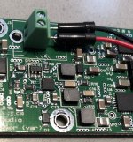
Hi Jan, I am afraid that I may have hurt my SilentSwitcher. Not exactly sure what is causing it, but this is what I see:
- the -V output gives 0 V: almost no voltage difference with ground
- L3 is cracked - see attached pic, don’t know what happened there!
Do you have any suggestions on how to go about troubleshooting or fixing?
Thanks in advance,
Maarten

- the -V output gives 0 V: almost no voltage difference with ground
- L3 is cracked - see attached pic, don’t know what happened there!
Do you have any suggestions on how to go about troubleshooting or fixing?
Thanks in advance,
Maarten

- Home
- Vendor's Bazaar
- SilentSwitcher - mains-free +/-15V and 6/5/3.3V power


