I'll try to find a problem. I do not understand the cause of these residual noises after loud signals. They are like murmur or chirping sparrows.That seems odd? Any thoughts on what could be going on?
Theoretically, the scheme for differential FF looks more beautiful than on AHCT595 registers.
If you have any ideas, I'll be happy to listen.
I'll try to find a problem. I do not understand the cause of these residual noises after loud signals. They are like murmur or chirping sparrows.
Theoretically, the scheme for differential FF looks more beautiful than on AHCT595 registers.
If you have any ideas, I'll be happy to listen.
Could it have something to do with propagation delay differences (i.e settling time) between the differential FFs & the 595 FF you were using before?
What exact chips were you using in both configurations - got links to their datasheets?
v2.5-2.6 74AHCT595 http://www.ti.com/lit/ds/symlink/sn74ahct595.pdf
v3.0 74VHC175 https://toshiba.semicon-storage.com/info/docget.jsp?did=17749&prodName=TC74VHC175FT
v3.0 74VHC175 https://toshiba.semicon-storage.com/info/docget.jsp?did=17749&prodName=TC74VHC175FT
Nothing obvious in the datasheets.
Are you sure you are still using a moving average filter with the Quad FF?
DSD input ->1D which outputs 1Q & 1Qbar
1Q connected to 2D which outputs 2Q & 2Qbar
2Q to 3D with 3Q & 3Qbar out
3Q to 4D -> 4Q & 4Qbar
4Q connected to 1D of next Quad Diff FF & and so on
Each Q & Qbar connected to series R for balanced output into transformer
Last edited:
Nothing obvious in the datasheets.
Are you sure you are still using a moving average filter with the Quad FF?
DSD input ->1D which outputs 1Q & 1Qbar
1Q connected to 2D which outputs 2Q & 2Qbar and so on
Each Q & Qbar connected to series R for balanced output into transformer
Yes, exactly as you wrote.
http://www.diyaudio.com/forums/attachment.php?attachmentid=662588&stc=1&d=1518689107
Attachments
There's one possibility - increased differential noise.
It's hardly common mode noise as this would largely be removed by the transformers on the outputs
AFAI see & I raised this question before - the possibility that connecting the Q outputs to both serial resistor & the next data input pin introduces some difference in Q Vs Qbar output - the result being extra differential noise introduced?
When doing differential output with 595s each output is driving into the same load
So maybe using moving average filter with differential FFs upsets the differential balance of the outputs?
I assembled the DSC layout on the differential FF 74VHC175.
Works badly. I again hear noise (murmur) as in the original non-differential DSC1 scheme. The overall noise level also deteriorated compared to v2.5 and v2.6.
Wow, that was fast. Good work PPY!
VHC175 looks pretty similar to AHCT595 WRT prop delay so that doesn't appear to be culprit.
Looking at FFT results there is dominant H2 which is pointing to a lack of symmetry or balance.
Driving same chips (595) with opposite signals appears to have better symmetry and hence cancellation of distortion.
As far as the noise is concerned is there any difference between VHC and AHCT besides different manufacturers version of the same thing?
Are the resistor networks same, ie; 32 x 8k?
A surprising result but nevertheless there is something to learn here.
T
One way of overcoming this issue & testing if it's really an imbalance in differential outputs is to disconnect the Qs from the following D inputs & instead use 595s in front of the quad FFs feeding their outputs into the D inputs of the quad FFs. That way there should be no imbalance between Q & Qbar outputs but it will introduce an extra bit of propagation delay in th e595s - doubt it will matter, though as these are low nS delays.
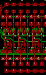
Just looking at your pcb & I first thought you had the wrong pinouts for the 175 FF but I think I see what you did & I'm wondering if it might have a bearing on the imbalance between Q & Qbar outs?
Correct me if I'm wrong but you seem to have no output resistor connected to Q1 output - instead you connected it to D2 (under the chip?) & the output resistor is connected to D2. This is the same scheme used throughout. I wonder if this is one additional source of imbalance between Q Vs Qbar outputs?
Maybe others can answer the implications of current being sourced/sunk at the Q pins but the pcb trace having the D input pins as spurs off this trace.
Alternatively, when you think about the design - connecting D inputs to Q outputs means that every pulse at D input will result in the pulse also being present on the connected Q output & causing a voltage spike through the connected resistor. Could this be the real source of the extra distortion? Normally it wouldn't matter when using FFs as a shift registers but when we have resistors connected to the Q outputs, it does, no?
Last edited:
Scrub that last thought - I wasn't thinking clearly - the pulse originates at Q1 & connects to D2 not the other way around - Doh!
I do not think that the resistor can significantly influence. I have retained measurements of the non-balanced version of DSC1. Very similar to the measurement of the version with FF. And most importantly, both options have an unpleasant correlation noise.Just looking at your pcb & I first thought you had the wrong pinouts for the 175 FF but I think I see what you did & I'm wondering if it might have a bearing on the imbalance between Q & Qbar outs?
Yes, you are right, not all resistors are connected directly to the outputs of Q. With two-layer pcb it is difficult to do otherwise. But this is a minor distance ~ 3mm.Correct me if I'm wrong but you seem to have no output resistor connected to Q1 output - instead you connected it to D2 (under the chip?) & the output resistor is connected to D2. This is the same scheme used throughout. I wonder if this is one additional source of imbalance between Q Vs Qbar outputs?
Maybe others can answer the implications of current being sourced/sunk at the Q pins but the pcb trace having the D input pins as spurs off this trace.
I want to say that the main problem is correlation noise, which was not in the previous version on AHCT595!Alternatively, when you think about the design - connecting D inputs to Q outputs means that every pulse at D input will result in the pulse also being present on the connected Q output & causing a voltage spike through the connected resistor. Could this be the real source of the extra distortion? Normally it wouldn't matter when using FFs as a shift registers but when we have resistors connected to the Q outputs, it does, no?
The fact is that in the scheme for FF we get a pseudo differential scheme. The signal is formed on a single shift register.
A variant with AHCT595 tru balanced. There are two symmetrical shoulder registers. And all the noise that appears due to mixing of a weak useful signal and analog noise is well compensated by the balanced circuit.
This correlation noise is very annoying. It appears as a tail after loud signals and looks like a murmur.
It seems to me that this option with FF is not worthy of further attention.🙁
Attachments
Last edited:
I do not think that the resistor can significantly influence. I have retained measurements of the non-balanced version of DSC1. Very similar to the measurement of the version with FF. And most importantly, both options have an unpleasant correlation noise.
Yes, you are right, not all resistors are connected directly to the outputs of Q. With two-layer pcb it is difficult to do otherwise. But this is a minor distance ~ 3mm.
I want to say that the main problem is correlation noise, which was not in the previous version on AHCT595!
The fact is that in the scheme for FF we get a pseudo differential scheme. The signal is formed on a single shift register.
A variant with AHCT595 tru balanced. There are two symmetrical shoulder registers. And all the noise that appears due to mixing of a weak useful signal and analog noise is well compensated by the balanced circuit.
This correlation noise is very annoying. It appears as a tail after loud signals and looks like a murmur.
It seems to me that this option with FF is not worthy of further attention.🙁
Can I buy this your pcb dsc v3.0 ?
Installed yesterday the dsc2 board from pavel and it smokes my beloved Es9018 Dac without break. The dac is powered by one Paul Hynes shunt pre regulator, the amanero is powered from one 3V3 shunt regulator. Sound is really fantastic! Great work Pavel!
Can I buy this your pcb dsc v3.0 ?
Do you really want to buy this version? 😱
Why? Do you have any ideas how to solve the problem?
Thank you. The period of tests, the search for the optimal design and components is complete.Sound is really fantastic! Great work Pavel!
I'm working on the final release. But I would like to hear from everyone who is interested in DSC - How do you want to see it?
Before the final release, I am ready to discuss your proposals.
Pavel: I wish for isolation between USB interface and DSC. Also, I would prefer the USB interface operated in slave mode, and the DAC PCB had a (better) XO on board, with a dedicated low noise LDO (LT-3045, etc). Then the clock could go back to USB interface through the isolators.
Also I would like to see pretty good current drive out of this, to drive amp input stages directly (or perhaps passive attenuators for some) as HQPlayer can control level, and very soon it appears more DSD capable VC are coming to other software players. Also at least 3.0 V out for 0dB signals.
I might like pre-mounted ICs as well, soldering SMD resistors by hand is no problem, but the ICs can be a little tricky for me.
Pavel: I wish for isolation between USB interface and DSC. Also, I would prefer the USB interface operated in slave mode, and the DAC PCB had a (better) XO on board, with a dedicated low noise LDO (LT-3045, etc). Then the clock could go back to USB interface through the isolators.
Also I would like to see pretty good current drive out of this, to drive amp input stages directly (or perhaps passive attenuators for some) as HQPlayer can control level, and very soon it appears more DSD capable VC are coming to other software players. Also at least 3.0 V out for 0dB signals.
I might like pre-mounted ICs as well, soldering SMD resistors by hand is no problem, but the ICs can be a little tricky for me.
Pavel, I totally agree with the above, but I'd go further and be more specific:
1. I'd love this to work with TP Hermes/Cronus combo.
The latter works well with all other DACs I tested, while DSC2 for some reason insists on direct Amanero connection. I shared the details with you before privately.
2. I'd like the ability to bypass the output stage and introduce my own. The unit sounds great with my solid state amps, but when I add it to my 300B tube amp... I guess we get too many transforms in the signal path: it sounds compressed.
In any case, it's a fantastic unit and I'll buy the finalized version in a heartbeat.
I believe DSC style designs require the DSDON and MUTE signals from the Amanero, since the TPA Hermes/Cronus has no provisions for those signals it will not work.
barrows luchoh, thank you. I will review your suggestions and answer later.
The DSC1 DAC as a way to understand how a simple DSD DAC actually works - Page 4 - DAC - Digital to Analog Conversion - Computer Audiophile
It is enough to replace two inverters with 74LVC1G04 at 74LVC1G34.
In the final version, this will be fixed.
Can this solution help you?1. I'd love this to work with TP Hermes/Cronus combo.
The latter works well with all other DACs I tested, while DSC2 for some reason insists on direct Amanero connection. I shared the details with you before privately.
The DSC1 DAC as a way to understand how a simple DSD DAC actually works - Page 4 - DAC - Digital to Analog Conversion - Computer Audiophile
It is enough to replace two inverters with 74LVC1G04 at 74LVC1G34.
In the final version, this will be fixed.
Last edited:
- Home
- Source & Line
- Digital Line Level
- Signalyst DSC1