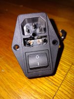
Is that the solder version or is it the faston version?
Or is it the faston version but soldered?
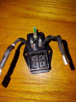
The heat shrink tube is an obstacle to clear view. It can be seen that there are sharp things sticking out at the right side.
Or is it the faston version but soldered?
The heat shrink tube is an obstacle to clear view. It can be seen that there are sharp things sticking out at the right side.
Both. Ground straight solder. Jumpers soldered on lower posts (still attached in photo), faston with solder above. I don't think enough solder as I was able to pull it off with needle nose. More like just enough to prevent it being lose feeling. So that connection not ideal.
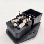
For the age of amp and amount of heat this part exposed to, the connectors weren't as bad as I had expected.
Now to remove power supply board and go over it. Waiting on FedEx, allegedly out for delivery.
Russellc
For the age of amp and amount of heat this part exposed to, the connectors weren't as bad as I had expected.
Now to remove power supply board and go over it. Waiting on FedEx, allegedly out for delivery.
Russellc
I do not understand the answers as the PEM can not be both. I would not know what is meant with jumpers either.
The question is simple: is your Schurter PEM a faston version yes or no?
If it is the faston version having been soldered that would be a user error. Sorry.
The question is simple: is your Schurter PEM a faston version yes or no?
If it is the faston version having been soldered that would be a user error. Sorry.
Last edited:
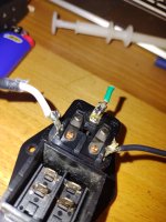
At the time I didn't like the idea, hard to get to and possibility of overheating as well. But I didn't like the idea of it just being a friction fit so ....removing it, was obvious not much solder. It pulled off without much pressure.
Then covered with shrink wrap and forgotten. Until now.
Russellc
Then covered with shrink wrap and forgotten. Until now.
Russellc
Is it that hard to say “yes” or “no”? Or even giving a reply to questions? I think it has been asked 4 times.
So you soldered that faston version and not even good enough. This overheated the PEM while soldering it (it is not meant to be soldered) possibly deforming/weakening it. Then the not well enough soldered connection was too high ohmic that generated heat over a longer time. Not a Schurter error or a fuse error, no a plain user error because the user did not like the idea of a friction fit (that is better than a solder joint). Well look where it got you.
So you soldered that faston version and not even good enough. This overheated the PEM while soldering it (it is not meant to be soldered) possibly deforming/weakening it. Then the not well enough soldered connection was too high ohmic that generated heat over a longer time. Not a Schurter error or a fuse error, no a plain user error because the user did not like the idea of a friction fit (that is better than a solder joint). Well look where it got you.
Last edited:

"What if I solder after connecting the faston?" <-- Actually, this was a thought that I had in my head. 😱
I never thought that this problem could occur.
Thanks to everyone who discussed it here to share knowledge in the community. 👍
I never thought that this problem could occur.
Thanks to everyone who discussed it here to share knowledge in the community. 👍
Don’t do it. The surface is too large (certainly the 6.3 mm version) therefor needing much heat over too long time and also a too long cooling down period for the melting/deforming/weakening plastic. The solder versions have smaller contacts meant to be soldered. The fact that the soldered wires could be pulled easily from the faston blades gave it away. The failure would not have happened if they would have been crimped.
Also soldering already crimped faston connectors (on wires) simply is bad practice.
If you like reliable stuff just crimp stuff meant to be crimped and solder stuff meant to be soldered. It is simple in fact and designed to be used like that.
Also soldering already crimped faston connectors (on wires) simply is bad practice.
If you like reliable stuff just crimp stuff meant to be crimped and solder stuff meant to be soldered. It is simple in fact and designed to be used like that.
Last edited:

Beyond making sure to have on/off switch of sufficient amp rating, I hadnt given a lot of thought about fuse holders and so forth in these all in one units. These First Watt clones pull a lot of juice and some of the extreme examples push that further, add dual mono parts, 10 amps switch maybe is on the edge? I bet my XA252 is,
On the feeling the drawer obsession, tonight the PoP amp's drawer isnt as hot feeling as last night, same temp as back panel.
On the feeling the drawer obsession, tonight the PoP amp's drawer isnt as hot feeling as last night, same temp as back panel.
Sorry... getting late, time to smoke cigar.... what is the solution here?
Do we have to check our amps?
Are you telling me that Tim Rawson's amps are perhaps safer? Fuse? We don't need no stinkin' fuse!
Can you please make an appropriate PUBLIC SERVICE ANNOUNCEMENT about this?
Thanks
Do we have to check our amps?
Are you telling me that Tim Rawson's amps are perhaps safer? Fuse? We don't need no stinkin' fuse!
Can you please make an appropriate PUBLIC SERVICE ANNOUNCEMENT about this?
Thanks
@tonyEE
As far as I understand so far, it seems the issue is due to the 2.8mm spades on the diyaudio store provide Schurter 4304.4045 PEM being different size than the rest of the 5mm spades on the PEM. Because of this, many folks end up soldering on wires to those smaller fuse tabs instead of using 2.8mm female crimped spades per the design. In taking that path of soldering instead of using crimped connectors, there is an inherent risk of melting the plastic holding the fuse tabs in place, which could result in poor contact with the fuse on the internal portion of the fuse box. That poor contact would/could then result in a higher resistance due to poor contact, increasing heat, which over time will fail the PEM in the fuse box. Folks who solder to the 2.8mm spade connectors on the store provided PEM and don't have this overheat issue are likely just getting lucky by not melting the plastic. Using 2.8mm spade crimp on connectors on the fuse tabs are the correct approach to avoid the issue identified, not soldering wires direct.
I believe this is the going theory that's been narrowed down by the experts. I'm probably wrong in my understanding, but the experts can correct the error of my understanding.
As for the diyaudio store back-panel provided PEM, the new version being sold as of this month no longer has this issue of different spade sizes, as the fuse connections are all internal, so only the line/load, neutral, and ground spades are the same size standard faston (all which I presume must be used with same size 6.8mm/0.250" female spade crimp connections --> no soldering=no plastic to melt).
Last edited:
This is right, But over the years this peak current occurs often (at each switch on procedure). And anywhere the resistance is significant for thermal stress. Internal corrosion (on the fuse holder e. g.) provide the same result of course.Just suppose the way it was till they went kaput. No CL-60 was hurt as there was none (AFAIK). If there was a CL-60 then it is even more strange as inrush current was limited in that case.
Also the loads impedance should be taken into account. The load is not a short circuit so to speak. Just as surge currents that always occur but are so short they usually don’t cause damage but it is a good thing to limit them. In the EU this is mandatory above 500VA.
The very best soft start is to limit inrush current and then bridge the thermistor. Just a thermistor is a tad too simple.
IMHO inrush currents are not the cause as the heat was there for a longer time. The inrush current lasts a few periods so hundred milliseconds tops. This is so short that no significant heat will occur.
P.S.: Under
The ultimate Inrush Current Limiter Solution for large Toroidal Transformers
you will find different solutions for inrush current limiters
Also the moment of switching it on is manual so random, thus inrush current is different at each time it is switched on. The randomness together with the CL60 makes that this is not the reason that the IEC inlet failed.
That nice randomness disappears when using soft start circuits that use the mains sinus for timing. About the worst are zero crossing SSRs for this particular purpose.
Also note that no Ampèremeter has been hurt to see what currents actually flow. Actual data is lacking. As said a 10A fuse holder implemented as designed must be able to be used till 10A continuously without any issue.
Last edited:
I know it is easier to engineer using edicts like “don’t use brand X parts” than it is to crunch the numbers and actually know what you are doing. To put it another way, if you don’t want to do the math, as Edward R. Murrow said “Good night, and good luck”.
A careful reading of the data sheet for the Schurter DD11 input module will reveal a wattage limitation for the fuse holder. It’s listed under several conditions but uses a graph that a value must be interpolated from. Similarly, a look at the data sheet for Littelfuse type 215 fuse, for example, will show the cold resistance and the dissipation at 1.5 times the rated current. You should calculate the wattage dissipated at the nominal and maximum currents you expect to run at, but also understand the reason the 1.5 times figure is given. For a 2.5A type 215 fuse, the fuse will hold at 3.75A for a minimum of 60 minutes. In the event of a fault, the fuse holder, if one is used, must be able to withstand the dissipation present until the fuse opens. Again, for the 2.5A fuse, this is 2.5 watts. Going back to the data sheet for the DD11, this clearly exceeds the acceptable wattage.
The point is, for a reliable application of an integrated power entry module, you need to do the math. Otherwise its “Good night, and good luck”!
That, and the switch is only rated for 10 amps, which is also under rated for some of these amps. As zenmod pointed out, not good for these class A amps, especially the dual mono ones. I dont think the switches are as big a problem as the fuse holder, but there you have it. Measured and math applied or not, that much is evident.
I will post a pic of the soldered posts, now with heat shrink. Small solder blob, nothing excessive. If the heat from this traveled down the wire, to fuse and then caused the damage it only did it on the line side. I have a number of these PEM units coming, one will be "sacrificed " by putting fuse in it and soldering the wire, heavily to see if this degree of damage occurs. Your math indicates under spec, and I agree.
BTW, never said "dont use" in fact just ordered several more. Clearly, this older version of PEM is either under rated or right on the line for these uses, andmany of us here are using these. I still feel damage occurred with the Mono block conversion, due to these specs. Will get to bottom.
For now, plan going forward will be to use the 16-20 amp rated high heat fuse holders, and keep baby sitters in use. With them, everything is cool.
Attachments
@Cyberpup - Lovely summary. Thank you.
Adding to your thoughts, DIYers may find IEC 60257:1968/AMD2:1989 and/or UL Std 512 of interest.
There are also excellent summaries and application notes for fuse drawer and fuse choices across the internet.
Both Schurter and Littelfuse have excellent (IMO) summaries of key findings along with recommendations.
Below is an excerpt from a Schurter document I had saved. If I find an link to the document itself, I'll edit or repost. At the moment, I think posting a photo of the excerpt is within bounds of copyright. The link to the main Schurter website is included to indicate the source, but the document itself isn't titled, and I am not sure if attaching the entire document would be allowed. I cannot copy any material from UL or IEC paid standards unfortunately (to the best of my understanding).
Please dont misunderstand, I'm not product bashing or pointing fingers at all. I just had this happen, likely by my own hand and now like most other areas, want to go over kill in the fuse holders. I never really gave a second thought about these 3 in one, and just bought more in fact. I would like to see If soldering those posts could cause damage, which is entirely possible. Maybe they were not pushed past spec, other than user error. If they survive test, (which is what Im thinking) doesnt make it proper but at least It can help me figure out why it failed.
Also, I've built a couple Amps that burn some power and that's another reason I'm looking for a bit more over kill in this area.. This one cooked pretty well so it got my attention. I made the incorrect assumption I wasnt pushing beyond spec of the part, or caused it to self destruct in some other fashion.
Once PEM sorted, on to power supply checking, then boards checking for possible error.
Back to playing.
- Home
- Amplifiers
- Pass Labs
- Shurter on/off fuse units