Ive built 2 of these regulators from The old GB.
But how can I make it go Down to 5 volt out.
I can only make it go down to 6.2v.
How?
But how can I make it go Down to 5 volt out.
I can only make it go down to 6.2v.
How?
It was not designed for 5 V and I am not sure if it will behave good enough but you can try.Ive built 2 of these regulators from The old GB.
But how can I make it go Down to 5 volt out.
I can only make it go down to 6.2v.
How?
First you need P1of higher value like 5k or more and decrease R3 and R12 to 3k3.
Good luck.👍
Any fruits born from offered gerbers? 😉
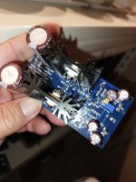
I will attempt to home-etch one (or two). Just came across this thread and it looks like a nice sunday afternoon project.
I changed the resistors to 3,3 k and without chansning the pot I got to 5v.It was not designed for 5 V and I am not sure if it will behave good enough but you can try.
First you need P1of higher value like 5k or more and decrease R3 and R12 to 3k3.
Good luck.👍
Nice🙂I changed the resistors to 3,3 k and without chansning the pot I got to 5v.
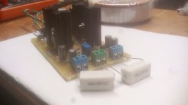

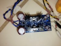
👍Its working perfectly..
10+22=6.8 Ω 1.113V-1.233
IRF510-9510 BF245B at 10ma 2sk170 China at 12ma
Many many thanks my friend. Damir.
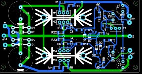
Damir,Updated schematic and BOM are here. To get better and more linear output impedance CCS (J2 and J3) is increased to about 10 mA and nfet used here should be chosed with the Idss of 10 mA or more. R2 and R9 are simple jumpers if Idss is close to 10 mA if higher then chose appropriate value to get about 10 mA.
Damir
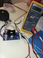
In my case R2 and R9 are 110Ω and measure on it about 660mv and 690mv . Must use simple jumpers on R2,R9 for better results?
Last edited:
You have CCS current set to about 6 mA (0.66/110), better if you can increase it to 10 mA. Tray with 22R.Damir,
In my case R2 and R9 are 110Ω and measure on it about 660mv and 690mv . Must use simple jumpers on R2,R9 for better results?
You can use jumpers too, it will get good result but there is no simple way to measure CCS current.
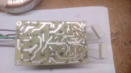
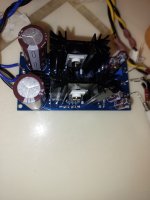
Very clean traces for a homegrown PCB!Its working perfectly..
...
Many many thanks my friend. Damir.


@dadod
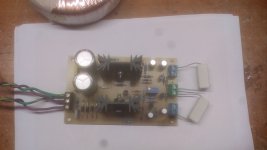
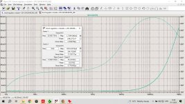
I have completed one board after a long wait due to my travelling. With R3 and R12 reduced to 10K from 15K and a VR of 1K in the P1 position, i am able to dial in to 7.5V lowest.
Loaded it with 50mA load at +/-12V. Worked right away....thank you so much for this nice and compact PSU. J2 and J3 idss are 9mA and 9.2mA.
Attachments
Last edited:
zoom777, nice, it worked OK. 😉
I don't remember if I mentioned before why there two pins for + and - output, if load (or what you want to drive from this regulator) is not very close to the regulator you should use two wires for each + and - output from the regulator and shorten those two wires at the load.
I don't remember if I mentioned before why there two pins for + and - output, if load (or what you want to drive from this regulator) is not very close to the regulator you should use two wires for each + and - output from the regulator and shorten those two wires at the load.
- Home
- Amplifiers
- Power Supplies
- Shunt regulator +-15V