Dadod.
Finnally i have some time to solder that reg.
One question....Which jfet did you choose...i have BF245C but pin positions are switched according to print ...am i right?
I have irf510 and 9520 in my desk... Do you think that it will be some difference in result for +- 15V rails?
Thank you.
Finnally i have some time to solder that reg.
One question....Which jfet did you choose...i have BF245C but pin positions are switched according to print ...am i right?
I have irf510 and 9520 in my desk... Do you think that it will be some difference in result for +- 15V rails?
Thank you.
Dadod.
Finnally i have some time to solder that reg.
One question....Which jfet did you choose...i have BF245C but pin positions are switched according to print ...am i right?
I have irf510 and 9520 in my desk... Do you think that it will be some difference in result for +- 15V rails?
Thank you.
I used 2N5486, BF245C is with to high Idss 12 to 25mA, you need BF245B.
Layout was made for 2N5486, if BF245B used just rotate it by 180 degree.
You can use IRF510 or 520, with 520 you will bet probably a bit lower output impedance, but with 510(it has lower input capacitance) it will be more linear up to 20 kHz.
Thank you.
I rotate them and first measure them with 9v battery and set bf245c to 10mA. 180r to 220r was ok.
Will report about sound.
I rotate them and first measure them with 9v battery and set bf245c to 10mA. 180r to 220r was ok.
Will report about sound.
Thank you.
I rotate them and first measure them with 9v battery and set bf245c to 10mA. 180r to 220r was ok.
Will report about sound.
Probably it's not possible to set it to 10 mA, look my previous answer.
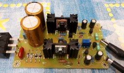
Finally i finished shunt regulator. Just couldn*t find time to do it till the end.
For fet i used 2n3189 one vas almost 10mA and one vas 12mA SG connected and measured IDSS so only that second one gets resistor set to 10mA. Can be done so?
Output is almost the same ... Output difference is 0.02V and output current is 100mA on + side vs 105mA on - side with the same value of shunt resistor. It is probbably because I used irf510 and irf9520. I wil order irf9510 but that was in my table.
Noise on scope is almost unmeasurable... Sound test in a few days. It will be on analog supply arround 14V for 2 pcs lme49990 in ak4490 dac Vs Kubota regulator which has more noise on output.
Thank you Dadod.
Attachments
Finally i finished shunt regulator. Just couldn*t find time to do it till the end.
For fet i used 2n3189 one vas almost 10mA and one vas 12mA SG connected and measured IDSS so only that second one gets resistor set to 10mA. Can be done so?
Output is almost the same ... Output difference is 0.02V and output current is 100mA on + side vs 105mA on - side with the same value of shunt resistor. It is probbably because I used irf510 and irf9520. I wil order irf9510 but that was in my table.
Noise on scope is almost unmeasurable... Sound test in a few days. It will be on analog supply arround 14V for 2 pcs lme49990 in ak4490 dac Vs Kubota regulator which has more noise on output.
Thank you Dadod.
You can use different source resistor for CCS.
When you say shunt resistor what do you mean? Total current per side is defined with DN2540 and its source resistor(that could differ as DN2540 could have different Idss). The shunt mosfet influence output voltage and output impedance.
I need to get + - 10V output. What do need to change?
Sorry I missed that post. Use transformer with 2x12 V AC and adjust output voltage with the trimer.
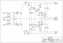
After long time I would like to edit this wonderful shunt regulator.
Instead unobtainable 2SK170 it's possible to use depletion mode mosfet LND150.
DN2540 is OK but DN2535 is OK too.
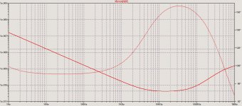
Attached last schematic and output impedance.
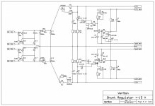
Instead unobtainable 2SK170 it's possible to use depletion mode mosfet LND150.
DN2540 is OK but DN2535 is OK too.
Attached last schematic and output impedance.
Attachments

If you are going to get PCB's made for the new version, I would be interested in one, or even the old version would be nice
I don't have any spare board and not going to order new ones, sorryIf you are going to get PCB's made for the new version, I would be interested in one, or even the old version would be nice
Hard to define. Reduce the input voltage until the current source output droops X percent? (Walk it past the "knee" of the Depletion MOSFET's I-V curve)? The output voltage will remain the same and the regulator's output will still be regulated . . . . But its available maximum output current is now X percent lower.
I use transformer with of 2x15VAC and that will give +-20VDC about, and that give 5V drop on DN2540 (DN2535).What is the dropoutvoltage?
- Home
- Amplifiers
- Power Supplies
- Shunt regulator +-15V