...or a single ccs-loaded pentode with a-g1 feedback, dc coupled to a mosfet concertina then going to the power amp.
Is it possible to get comparable performances for a mosfet concertina in this scenario of very wide voltage swings?
Is it possible to get comparable performances for a mosfet concertina in this scenario of very wide voltage swings?
Last edited:
I think it will work well, as long as the DC conditions are right and there is enough headroom. Concertinas can't create as much AC swing as an LTP with the same given B+, so you just have to be mindful of that in the design.
I'd feed it with a very clean supply to avoid PSRR issues, which aren't as much of a problem with an LTP.
I'd feed it with a very clean supply to avoid PSRR issues, which aren't as much of a problem with an LTP.
...or a single ccs-loaded pentode with a-g1 feedback, dc coupled to a mosfet concertina then going to the power amp.
A single pentode doesn't benefit much from ccs loading. a-g1 feedback is not necessarily any better than cathode degeneration, depending on circuit specifics. Pentode is not as linear as triode. The big benefit is less Miller, if that's an issue. At the end of the day you may find that Pete's single triode into pentode LTP is a pretty well thought out topology.
Is it possible to get comparable performances for a mosfet concertina in this scenario of very wide voltage swings?
Yes comparable but comparing 2 suboptimal circuits misses the point. You need lots of swing for your chosen final stage and concertina is inherently inferior in that respect.
Last edited:
SpreadSpectrum, dgta,
thank you very much for your suggestions. I really appreciate the time you both are dedicating in suggesting possible solutions to approach and highlighting weak points of other solutions.
I go on working on the pentode LTP as well.
I would keep Millett solution as last to try, even if it will most probably guarantee better results compared to how I can optimize circuits by now.
The schematic shown in post #57 of the UNSET thread shows a mosfet PI between the driver and output stages. This is a 20 watt amp that runs 50C5 tubes from an old radio.
I tried both a budget Edcor transformer and a similar mosfet PI in front of the UNSET board for the 250 watt P-P tests.
The mosfet had significantly better performance due to better balance, and frequency response. It was powered from the 170 volt screen supply and only needed to make a couple volts of drive.
Thank you again George,
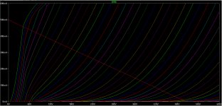
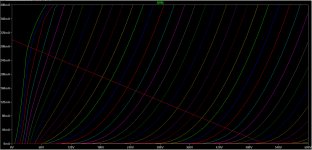
here I need to swing around 240Vpp to reach full power, so a total different task, but I will try it anyway.
here I need to swing around 240Vpp to reach full power, so a total different task, but I will try it anyway.
I attach here the curves of the KT88 in this configuration, together with the 4k Raa loadline.
I've had a stop on simulations on the pentode LTP driver, but I've has some more ideas to try. I remember it still wasn't balanced.
I would still prefer to keep two stages only.

I've had a stop on simulations on the pentode LTP driver, but I've has some more ideas to try. I remember it still wasn't balanced.
I would still prefer to keep two stages only.
Attachments
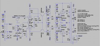
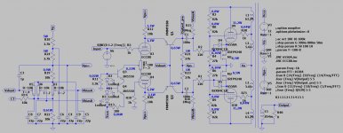
I would like to build this amp in the early months of 2020, so I update this thread with some further simplification of the PSU and with 6550A instead of KT88. On simulations it gives 100 Wrms with around 3,4% THD and a DF of 2,2 with 860 mVrms at its input.

Do you see any drawback in supplying the preamp and biasing the output tubes that way?
Thanks in advance,
Roberto
Code:
Harmonic	Frequency	 Fourier 	Normalized	 Phase  	Normalized
 Number 	  [Hz]   	Component	 Component	[degree]	Phase [deg]
    1   	1.000e+03	4.009e+01	1.000e+00	   -0.90°	    0.00°
    2   	2.000e+03	3.084e-02	7.692e-04	  -90.40°	  -89.51°
    3   	3.000e+03	1.250e+00	3.118e-02	    4.36°	    5.26°
    4   	4.000e+03	2.596e-03	6.476e-05	  105.21°	  106.10°
    5   	5.000e+03	4.864e-01	1.213e-02	 -175.26°	 -174.37°
    6   	6.000e+03	5.678e-04	1.416e-05	  -70.21°	  -69.31°
    7   	7.000e+03	2.439e-01	6.084e-03	   -0.26°	    0.64°
    8   	8.000e+03	4.336e-04	1.081e-05	   23.30°	   24.20°
    9   	9.000e+03	1.224e-01	3.054e-03	  165.00°	  165.89°
Total Harmonic Distortion: 3.414944%(3.424032%)
Do you see any drawback in supplying the preamp and biasing the output tubes that way?
Thanks in advance,
Roberto
Attachments
In real life, the FZT558 base terminals must be fixed with a stable, low impedance voltage - preferably a voltage regulator. The difference in measurement (and audition) is clear.
Also, in practice, Vps+ will need to be regulated, if current sources are not used in the R12 & R20 positions; I find it better (and the circuit to be simpler) with the current sources.
Tail current source bias should be OK, for the driver.
Also, in practice, Vps+ will need to be regulated, if current sources are not used in the R12 & R20 positions; I find it better (and the circuit to be simpler) with the current sources.
Tail current source bias should be OK, for the driver.
For push-pull with shunt cascode LTP the base currents for the FMMT558's are in opposite phase (constant current drawn from the supply), so I would think that the benefit of a voltage regulator would be less than for a single ended design. Also Zintolo is decoupling to the positive supply which significantly improves PSRR when using resistors instead of CCS as the load (again this only works well for the LTP arrangement).
A lower impedance supply would be better - my version of this has about 1.2mA through the voltage divider network with base current of ~0.015 mA per transistor (total base current 2.5% of voltage divider current).
A lower impedance supply would be better - my version of this has about 1.2mA through the voltage divider network with base current of ~0.015 mA per transistor (total base current 2.5% of voltage divider current).
Thank you very much Rod and tikiroo,
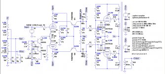
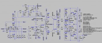
I've divided by 10 the values of the voltage divider for the base of the BJTs and adjusted the resistors of the PSU accordingly. Will it be enough being a PP?

Now I have 3 mA across the voltage divider to the base of the BJTs, so their total base current is 1% of it. I've reported power dissipation of each component to be able to determine a preliminary BOM.
As for the voltage supply, I would use a bridge rectifier going to a first 470 uF 550 V cap, then split the PSU in stereo with 10 Ohm to 470 uF 550 V cap for each channel. Each channel will have also its own voltage divider for BJTs and bias (5k single bias will be two 10k in parallel with 1 uF each).
-160V for the two 27k phase splitter's load resistors will be obtained by a 0-120V secondary bridge rectified with the same CRC arrangement for each channel.
-12V for the phase splitter's CCS can be taken from heaters (capacitor coupled then bridge recified?), and heaters' central tap will be connected to the top of R22 through a 10k resistor.
I'm thinking about a grill on the bottom of the amp plus some clearance on the sides of the top plate, in order keep air flowing and cooling the whole amp.
Do you see something more I'm missing?
I've divided by 10 the values of the voltage divider for the base of the BJTs and adjusted the resistors of the PSU accordingly. Will it be enough being a PP?
Now I have 3 mA across the voltage divider to the base of the BJTs, so their total base current is 1% of it. I've reported power dissipation of each component to be able to determine a preliminary BOM.
As for the voltage supply, I would use a bridge rectifier going to a first 470 uF 550 V cap, then split the PSU in stereo with 10 Ohm to 470 uF 550 V cap for each channel. Each channel will have also its own voltage divider for BJTs and bias (5k single bias will be two 10k in parallel with 1 uF each).
-160V for the two 27k phase splitter's load resistors will be obtained by a 0-120V secondary bridge rectified with the same CRC arrangement for each channel.
-12V for the phase splitter's CCS can be taken from heaters (capacitor coupled then bridge recified?), and heaters' central tap will be connected to the top of R22 through a 10k resistor.
I'm thinking about a grill on the bottom of the amp plus some clearance on the sides of the top plate, in order keep air flowing and cooling the whole amp.
Do you see something more I'm missing?
Attachments
> For push-pull with shunt cascode LTP the base currents for the FMMT558's are in opposite phase (constant current drawn from the supply), so I would think that the benefit of a voltage regulator would be less than for a single ended design.
Yes, SPICE will probably not report any distortion from this mechanism. But it models all instances of the 558 as exact matches, and will hide the deviations from real life. Hfe is a very badly-controlled parameter! The resulting distortion will look small compared to the whole amplifier, but I find it worth attending to these kind of flaws, when the best possible sound is the objective.
Yes, SPICE will probably not report any distortion from this mechanism. But it models all instances of the 558 as exact matches, and will hide the deviations from real life. Hfe is a very badly-controlled parameter! The resulting distortion will look small compared to the whole amplifier, but I find it worth attending to these kind of flaws, when the best possible sound is the objective.
Thank you for your reply Rod,
will it cause the gain of one side of the amp to be different, or will it cause also other issues? If it's just a matter of one side gaining differently, wouldn't the pot on ECC88's cathodes adjust those differencies?
Thanks in advance,
Roberto
will it cause the gain of one side of the amp to be different, or will it cause also other issues? If it's just a matter of one side gaining differently, wouldn't the pot on ECC88's cathodes adjust those differencies?
Thanks in advance,
Roberto
It adds a little (level-dependent) non-linearity to the output.
It does not change the overall gain figure, so a static offset will not make a difference.
It does not change the overall gain figure, so a static offset will not make a difference.
Perhaps I did not explain it very well! Here is some more detail.
The base current does not directly affect the small-signal gain. but the base current flows from the base voltage-source. The base current also varies with the signal, so that creates voltage drops across any impedances in its circuit-loop. You can think of the base current as an error. We would like it to be zero, like a FET, but we don't use FETs here, because high gm at low current is even more important, and with push-pull the very bad matching of FETs makes things worse.
With a push-pull stage, it is the difference in base currents that flows in the base supply. This variation can contain different harmonics, because the base-current differences get wider with increasing output.
Having signal-voltage drops at the base affects the anode voltage, and it can be enough to generate the harmonics in the output.
If you want to use LTSPICE to look at the possible effect of Hfe matching, you can do it:
- go to the directory {My Documents} LTSPICEXVII/lib/cmp and open standard.bjt with an editor. Copy the line beginning:
.model FMMT558 PNP (IS=7.84E-14 NF=1 BF=210 ...)
- paste the line underneath, and change the .model name to FMMT558-LBF
- change the forward gain parameter BF=180
That gives you a model with Hfe of 180 instead of 210.
Use the new model on one side of the PP pair.
Look at the harmonics from the driver output, taking careful note of the 5th and 7th. Don't just look at THD! Maybe you can optimise values to tackle any problems.
Hi Rod,
what a detailed and clear explanation, now it's very clear.
Thanks for the tip with LTSpice, I will try it this evening and report.
Usually I try to have 5th at least 1/10th of 3rd, but it is not always possible.
I will also try to simplify the supply of the base of the BJTs with a trimmer like for bias, and then see benefits of a stabilized supply vs this one.
Thanks!
You will need a separate bias pot for each output tube too, as matched tubes don't really exist either. If you do find a matched pair, they will age differently.
I've implemented the scheme to add only distortion as feedback to the phase splitter, and simulations (being only simulations, I know!) are outstanding:

DF is 135 and this is the distortion at 1 Wrms:
and this at 80 Wrms:
DF is 135 and this is the distortion at 1 Wrms:
Code:
Harmonic	Frequency	 Fourier 	Normalized	 Phase  	Normalized
 Number 	  [Hz]   	Component	 Component	[degree]	Phase [deg]
    1   	1.000e+03	4.072e+00	1.000e+00	   -0.65°	    0.00°
    2   	2.000e+03	6.418e-06	1.576e-06	  -80.41°	  -79.76°
    3   	3.000e+03	8.522e-06	2.093e-06	   19.72°	   20.37°
    4   	4.000e+03	2.963e-08	7.276e-09	    3.45°	    4.10°
    5   	5.000e+03	2.573e-08	6.318e-09	  -16.66°	  -16.01°
    6   	6.000e+03	1.781e-08	4.373e-09	    6.12°	    6.77°
    7   	7.000e+03	1.392e-08	3.418e-09	  -12.31°	  -11.66°
    8   	8.000e+03	1.418e-08	3.482e-09	  -18.83°	  -18.18°
    9   	9.000e+03	1.783e-08	4.378e-09	    1.75°	    2.40°
Total Harmonic Distortion: 0.000262%(0.000000%)
and this at 80 Wrms:
Code:
Harmonic	Frequency	 Fourier 	Normalized	 Phase  	Normalized
 Number 	  [Hz]   	Component	 Component	[degree]	Phase [deg]
    1   	1.000e+03	3.581e+01	1.000e+00	   -0.66°	    0.00°
    2   	2.000e+03	4.629e-04	1.292e-05	  -81.29°	  -80.64°
    3   	3.000e+03	1.066e-02	2.977e-04	   22.08°	   22.73°
    4   	4.000e+03	6.059e-06	1.692e-07	  -45.95°	  -45.30°
    5   	5.000e+03	2.669e-03	7.452e-05	 -143.90°	 -143.25°
    6   	6.000e+03	4.076e-06	1.138e-07	  145.98°	  146.64°
    7   	7.000e+03	1.216e-03	3.396e-05	   44.90°	   45.55°
    8   	8.000e+03	1.538e-06	4.294e-08	   25.22°	   25.88°
    9   	9.000e+03	5.248e-04	1.465e-05	 -123.60°	 -122.95°
Total Harmonic Distortion: 0.030942%(0.030936%)
Attachments
- Home
- Amplifiers
- Tubes / Valves
- Shunt Cascode Driver meets UNSET for Push-Pull