I did with one of my prototypes, took flat (ribbon) copper braid wire 1.5mm2 (4mm width), wrapped it with Nomex self-adhesive film all over entire length. Quite time consuming job to say at least. All secondary sections were connected in series to form 5 Ohm impedance.I wind with all the secondaries in parallel, but the question is if has anyone wound the secondary in series with a similar diameter as the parallel configuration, using Litz wire?
Attachments

Yeah I know about that, but what if you are winding an output transformer for general use? I mean what if you plan to sell 3.5K to 8 ohms SE transformer and you don't know if the buyer will use it with 300B or a pentode? Will a pentode Rp affect the load that much? Obviously not!You completly neglecting the tube parameters?
Actually the equivalent resistance of the generator, which is tube with load,
is close to parallel value of
Ri = internal resistance of the tube
Rload = Z primary
in parallel
So more accurate and very different value is
[(Ri x Rload) / (Ri + Rload)] / (2 Pi f)
Many books including RDH4 , Wolpert, etc use only Zp for that purpose.
BTW winding a transformer without considering tube Rp will end up with higher Lm and better bass response and also better high frequency response due to not taking Rp in series with L leakage.
Everything else depending on these first step parameters...Yeah I know about that, but what if you are winding an output transformer for general use? I mean what if you plan to sell 3.5K to 8 ohms SE transformer and you don't know if the buyer will use it with 300B or a pentode? Will a pentode Rp affect the load that much? Obviously not!
Many books including RDH4 , Wolpert, etc use only Zp for that purpose.
BTW winding a transformer without considering tube Rp will end up with higher Lm and better bass response and also better high frequency response due to not taking Rp in series with L leakage.
behaviour in HF domain depends on winding arrangemnet and other factors
but totaly opposite calc without specific equivalent R generator will end with lack in bass, bigger phase roll-off in bass.
.
Most of the literature inclouding equivalent simplified system as driver, consisting of 2 elements.
Voltage source that is tube with amplification as the stage, and Rsource in series, as equivalent source resistance.
.
And ofcourse that we can use same OT but with tubes that has similar internal resistances, and close amplification in stage.
.
Also we can use same OT for tubes with lower internal resistance BUT only if Cirrent is not higher, and load line is acceptable. Other way we wil loose LF...
.
(Typical example for this is 211 and 845 tubes - big difference in Ri, double value, but people using same OTs neglecting that fact... 🙁 )
.
I am afraid that with pentodes in SE mode decent OT is very dificult to design. Because of huge Ri, Lp become too high leading in too many windings, too much capacitance and everything else unwanted.
Are you sure about it? Here is a screenshot from RDH4, output transformer section:but totaly opposite calc without specific equivalent R generator will end with lack in bass, bigger phase roll-off in bass.
As you can see Low F falls where RA is equal to 2πf*Lo , so Lo = RA / 2πf
And RA equals to RL in PARALLEL to (Rp + Rw), so what happens if you take Rp into account? RA would be lower, so your calculated Lo would be lower, right?
behaviour in HF domain depends on winding arrangemnet and other factors
Of course it depends on L leakage and shunt C, and in the spreadsheet it is only used for estimation of Hi F roll off and resonance.
I didn't mention such thing. Connecting secondary layers in series with in phase polarity does not increase, in fact it decreases to an extent, depending of the turns ratio, primary to secondary capacitance.50AE mentioned several times about not connecting the secs in series as this may increase inter winding C.
Andy.
However, it can greatly affect capacitance distribution, often for the worse. Secondary layers in parallel act as shunting screens, that is, only one path towards ground. Interleaved interfaces can be looked upon as multiple coexisting transformers, all bridged together by capacitive currents. Series secondaries allow that to happen, and HF performance often gets degraded.
For low turn, low leakage transformers, one can get away with series secs, but one should be careful with high Ls transformers. For example, pentode stage OPTs are such. In such case, the constructor should aim for high Lp, low Cps, high Ls.
Thank you 50AE I misunderstood the difference. After I've wound a few I'll hopefully start to develop a deeper understanding & re-fine the process.
Hope this thread doesn't turn into another prolonged argument about the minutia of arcane parameters like it did at the start. I'll post some pics soon & get the thread back on track.
Andy.
Hope this thread doesn't turn into another prolonged argument about the minutia of arcane parameters like it did at the start. I'll post some pics soon & get the thread back on track.
Andy.
Yes I am.Are you sure about it?
Your spreadsheet is not good and will mislead users.
.
People didnt take a note because it is complicated to trce and identify the formulas in Excel cells.
I can recommend Matcad soft where all the formulas are written in the native math form and it is clear to read...
.
(Please take a look at the page that You from rdh that You posted..,)
.
Yes I am.
Your spreadsheet is not good and will mislead users.
.
People didnt take a note because it is complicated to trce and identify the formulas in Excel cells.
I can recommend Matcad soft where all the formulas are written in the native math form and it is clear to read...
Oh sorry, probably I couldn't explain my point well enough; I meant aiming for a little more Lo (or Magnetizing Inductance) wouldn't hurt, and it will lead to better bass response not weaker bass, because as you mentioned before, Rp (plate resistance of the output tube) is in parallel with RL (reflected load into primary or Zp). So if we don't take Rp into account it would lead us to a bigger value for Lo, not lower number.
Also if you look carefully in the spreadsheet formulas you will see that this calculated inductance will not play a part in further calculations and it is only there for seek of knowledge! Actually primary number of turns is practically always calculated based on the Bac and Bdc (AC and DC flux desity), which is entered by the user.
BTW I'm sorry if I upset you with my words, it's all misunderstanding. I really learned a lot from all you guys and still I'm learning and improving. Also your method for measuring Relative Permeability of core material really helped me, Much appreciated.
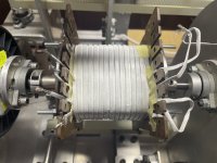
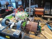
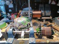
First proper OPT wind for a PPP triode AB2 amp. 2P of primary, 1/3 of secondary & 1 layer of 4P laid down, se pic.
BTW, how do others deal with partial winding layers? EG first pri wndg = 3 1/2 layers, popped the 1st sec wndg - 34T of 0.72mm in the 1/2 of layer left, but wondered if this is the EMF best coupling. So, is it better to center a partial layer, spread out the turns to fill full width of window or do as I have done to preserve/get the best layering?
As you can see the 1st layer of the next pri doesn't sit well.
Andy.
Attachments
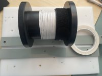
Best solution - multifiliar or foil.
Second solution - spread them evenly with air pockets, glue the winding to avoid misalignment or add threads to fill the space.
Second solution - spread them evenly with air pockets, glue the winding to avoid misalignment or add threads to fill the space.
For minimum winding higth and leakage inductance multifilar or foil
For minimum capacitance spread out winding
For minimum capacitance spread out winding
Probably better to design the transformer so all layers are either full or close enough to full, if this means that the impedances are not exact but only close to the design target that's ok ie if you design for 2.5K primary and by juggling the primary and secondary turns AND wire size you end up with full layers and 2.1K primary that's ok, the Lux transformer I recently rewound was marked 5K but measured 4.4K - designing and making an output transformer almost always results in making a compromises.
Thanks all. By multifilar I presume that means a sec 1/2 of width for instance that one winds 2T of pri to 1T of sec on the same layer, but in that case pri/secisolation is compromised isn't it?. Foil, how does that work re turns ratio? If I was to use 1 layer of foil, that's 1T?? Looks like spreading out turns is the best solution here but it don't half make winding the layer on top more difficult which means gaps like in the pics which means less window fill.
I have 2150T pri and 102T sec with a 2P, S, 4P, S, 4P , S, 2P layering, 2 x S is one layer so I guess I could have added more pri T or jiggled turns ratio/layering so that sec is two layers, ehm. What's the consensus re what I've already wound IE 1/2 layer of sec (you can see where it is by the gap, sec is on the LHS) with one layer of pri on top: remove what I've done & redo?
Andy.
By multifiliar we mean, winding multiple wires in parallel on the same layer to fill up more length of space.
Let's say, your whole layer length is 50mm and you need to wind 10 turns. To fill it up with a single conductor, it needs to have 5mm of diameter. That might be perhaps overkill in terms of low Rdc and winding space for your project.
An alternative is 10 conductors of 0.5mm per turn, or 5 conductors of 1.0mm. You decide by your required winding VA.
Right, you mean multiple wires but of the same winding, IE the secondary & not pri & sec. So instead of using 0.72mm use a lower gauge, say two turns in parallel of 0.35mm connected together at each end. I'll pull off the last two layers & redo as suggested. Using a lower gauge wire dia paralleled/bifilar means I could probably use 0.12 Nomex on top so the next layer sits well.By multifiliar we mean, winding multiple wires in parallel on the same layer to fill up more length of space.
Thanks again for the advice, Andy.
Remember that current density is reversely proportional to the cross section of wire, not its diameter, Meaning that instead of one 0.7mm wire , you sould use two 0.5mm wires in bifilar configuration.So instead of using 0.72mm use a lower gauge, say two turns in parallel of 0.35mm connected together at each end.
As sajadho1988 says, 2x0.5mm wires give an equivalent current density - you do though have a bit of leeway with the wire sizes - if you can't fit 51 bifilar turns of 0.5mm wire in the winding window then going down slightly in wire size should also be ok, and could give you a solution that works, here's a chart I found in an old German magazine, I copied it into an Excel table - a single 0.7mm wire is good for 980mA - 2x0.5mm wires will be good for 1000mA ie slightly more - and 2x0.48mm wires will good for 920mA ie slightly less. This is based on a current density of 2.5A/sqmm which is reasonably conservative, when listening to music a 22W amp will be running at well under 22W and possibly under 10W most of the time.
Attachments
Thanks both. I've been using the attached chart for years, but actually calculating current density looks a better way. I used two 0.63mm wires in the end as that was the best I had. I'm currently about half way through the 1st OPT tfmr wind.
BTW what do others do regards insulation between layers of the same winding? Insulate every layer or just between primary & secondary layers?
Cheers, Andy.
BTW what do others do regards insulation between layers of the same winding? Insulate every layer or just between primary & secondary layers?
Cheers, Andy.
I use insulation between layers of the same winding not just because it may decrease winding capacitance, but more importantly because it helps the regularity of layers, which is important in decreasing leakage inductance.BTW what do others do regards insulation between layers of the same winding?
I measured that when I use insulation between the same windings, I can wind up to 85% of the window, but whenever I don't use insulation i.e. in the case of PSU chokes, I can only wind up to 80% of the window! This means that using insulation may seems to occupy space but in reality it saves space by increasing winding regularity.
0.08mm Nomex is perfect for the job, but I used 0.10mm Presspahn (pressed paper) with the same results.
- Home
- Amplifiers
- Tubes / Valves
- Show your transformer work (gallery)