Hi
50AE
Many thanks for sharing your know-how
It's this arrangement better for hight Z like >5KOhm or so with many layers I think so
In my case eatch section is made of 3 layers, 9 layers total
I'm thinking about the transformer shown in Audiophile n°37 Push pull of 6336 cathodyne output stage.
where P and S are winding together (Bi wiring).
Z primery 600Ohm don't remember exactly
Yan
Hi Yan,
The optimality of this arrangement is for less interleaving settings with big packages, primary package with 4 and more layers. However in some projects, it can be also worth rotating a 3P package.
As for bifiliar winding with a ratio different than 1:1, there will be a high capacitance, so it is worth using this with a very low driving impedance.
As for bifiliar winding with a ratio different than 1:1, there will be a high capacitance, so it is worth using this with a very low driving impedance.
Like Circlotron ... his driving Z is low, about 100Ohm with 6P36C
Like Circlotron ... his driving Z is low, about 100Ohm with 6P36C
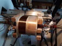
Some pics
Attachments
Last edited:

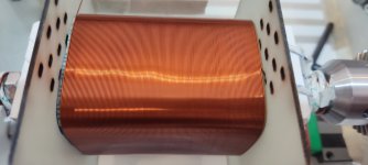

I like the bobbin structure ... I have that info on a sheet in Cyrillic, which I cannot read, but the images are self explanatory.
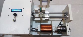
Your use of a collet on your winding shaft is a nice touch, too.
Your use of a collet on your winding shaft is a nice touch, too.
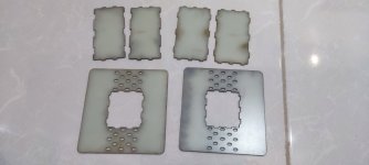
Good work - very neat, I assume the bobbin is held together with glue, do you cut the pieces by hand or are they laser cut ?
Thanks, I used super glue for that. The bobbin was from 1.6 mm fiberglass sheet and I used laser cutting.Good work - very neat, I assume the bobbin is held together with glue, do you cut the pieces by hand or are they laser cut ?
I was wondering over winding layer & tidiness remarks........what dielectric material are you using between layers ? Kellogs paper ? Yell insulating tape ? These can have a large influence on parasitics.
Bench Baron
Bench Baron
I use Kremple Presspahn as insulation. Thickness is 0.1 mm between the same windings and two layer of 0.2 mm as wrapping between different windings. Dielectric constant of this material is close to Nomex and maybe a little less, but this stuff need varnish which I use vacuum impregnation at the end with around 30 percent increase in overall shunt capacitance.what dielectric material are you using between layers ? Kellogs paper ? Yell insulating tape ? These can have a large influence on parasitics.
Partridge /Williamson of 1950/60 days famous for their complex output transformer designs used kelloggs paper and end dip seal only. Wax those days. Sowter til they were Carnhill did sim but used yellow tape and polyurethane varnish. Vacuum impregnation increases the dielectric properties/capacitance which one is desperately trying to avoid....Great for mains trafos as full impregnation reduces lamination buzz.
Good stuff,.... Keep at it;
Good stuff,.... Keep at it;
The amount of capacitance increase will highly depend on the degree of porosity of the dielectric. The lower it is density, for example some papers, meaning a higher air pocket quantity vs solid amount, the more detrimental the impregnation effect. On solid dielectrics where there's nothing to impregnate except space between turns, no big deal.
Indeed vacuum impregnation increases the capacitance depending on the varnish. I use electrical varnish and it always increases the total shunt capacitance by about 30 percent which I take into account in the design.
I found that vacuum impregnation of the OPT has some advantages; it reduces the 'singing' and also I found that after impregnation the turn ratio always increases which I assume is due to insulation effect of varnish on some shorted wires with defected enamel. Also I found that without impregnation turn ratio decreases in time, which I also assume is as a result of wires rattling and robbing against each other and causing the enamel to disappear in time.
I found that vacuum impregnation of the OPT has some advantages; it reduces the 'singing' and also I found that after impregnation the turn ratio always increases which I assume is due to insulation effect of varnish on some shorted wires with defected enamel. Also I found that without impregnation turn ratio decreases in time, which I also assume is as a result of wires rattling and robbing against each other and causing the enamel to disappear in time.
Hi
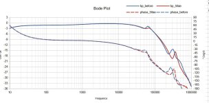
I promised it, I finally did the test of parallel serial connections of the secondaries in your way 50AE.
As I was using REW and a 24/192 external sound card, the measurements were limited (about 100kHz) to see the differences and
square response still similar in both cases.
I acquired a powerful digital scope Tiepie hs5.
Here is the phase frequency answer showing the difference between the two arrangement
I'll keep this good method
Many thanks 50AE to share your knowledge
Yan24
Attachments
Hi YanSome pics
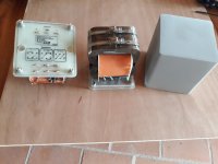
Where we can find these metal "tiny sheets with screws" for make tight C half's of core?
I don't know the name, You have 2 of them, per 2 x C, on Your finished transformer...
thamks
Hi Yan,
Thank you for contributing towards the experiment.
Now we can observe that the differences in this case are tiny.
Did you try the reverse-winding capacitance dumping techniques in your project? Usually, better benefits come from combining the two.
There is a third technique I'm using, especially valid for SE transformers, is the attempt to maximally equalize P/S capacitance by combining capacitance dump + dielectric epsilon and thickness.
Usually, the less amount of P/S interfaces, resulting into higher layer amount primary packages there are, the more benefits you'll acquire from these techniques.
Hi
Zoran
I use stainless steel clamps for building ventilation. There are diameters up to 250 to 300mm
50AE
I was not able to try this technique in this project. I think the schema must start and end with a primary.
In this case, I reverse the winding direction of the last primary (outside) and I find the HT layer in front off the secondary.
On this project I used a differentiated thickness between HT and the anodes junction. In my case between mass and cathodes of 0.2 to 0.7mm.
Has anyone heard the idea that the mass of the primary should equal the mass of the secondary ? I read that about tesla coils and wondered if it applied elsewhere ?
.
.
If you equalize the Rdc losses vs reflected impedance, that is, the losses are the same from the primary, as the ones from the secondary, do the math and you'll see the copper masses will be also equal.
- Home
- Amplifiers
- Tubes / Valves
- Show your transformer work (gallery)