Since i have time, i think i will try some jumpers to easily remove/put in place the C4 cap, just for flexibility. (Simple ones).
Thanks to both for your quick answers.
Thanks to both for your quick answers.
So if I was to use a single transformer using one secondary per channel, how large of a transformer would I need?
I always like something other than, "because I said so," you don't learn anything that way. Teach us Mark....
JT
JT
I will try...
First Watt Amp requiring 24V DC are using transformer with an output voltage of 18v (AC, RMS). Peak output would be 18*sqrt(2)=18*1.414=25.45volts. Then the bridge rectifier is taking something like 1.6volts to give 23.85volts.
For F5 Turbo V2 https://www.firstwatt.com/pdf/art_f5_turbo.pdf 48Volts DC is needed, 36volts @transfomer output is suggest. (36*1.414)-1.6=49.3
So, if i were to using transformer + bridge rectifier + bank of caps, i would go with a 28volts @output transformer (28*1.414)-1.6=37.9 volts.
[26v output would give (26*1.414)-1.6=35.16, might be too low?. Bridge rectifier voltage drop increasing with current, one might use 2volts... hence 28v transformer]]
There are websites to do a betterwork than that i remember.
That's what i learned / think i have learned.
If mistaken, please tell me! [i might have misunderstood "how large"... If power rating, then yes, i have misunderstood]
Last edited:
Recommended smps for the amp is 150watt.
Linear psu is less efficient but 200watts should cover the difference.
Yet, given the price difference between 200va and 300va is relatively small, i personnaly would go with 300va.
More freedom if re-used for a later project, but that s me.
Linear psu is less efficient but 200watts should cover the difference.
Yet, given the price difference between 200va and 300va is relatively small, i personnaly would go with 300va.
More freedom if re-used for a later project, but that s me.
I used a 300VA transformer, and your after ~36VDC, loaded for a Ship so 28VAC secondaries.Thanks. I was looking to know if I would need a 200 or 300KVA transformer.
^ 😳
Should be 300 VA.
I have XRK single phase SLB boards already, so 30VAC secondarys are probably better.
Should be 300 VA.
I have XRK single phase SLB boards already, so 30VAC secondarys are probably better.
@Mark Johnson hello, I could use some troubleshooting suggestions with Missouri FE cards.
At power up with ~36V, R6 on one channel went up in smoke. I cleaned and inspected all the solder joints for bridges and cold joints and replaced R6 with another 47R resistor, and checked L1 to make sure it wasn't shorted (because it was easy to check). With the good channel, I hooked it to a variable bench power supply with inputs shorted, IC's in and stepped it up in increments to 36V. I never saw more than a 20mA draw, and I was reading about 27.5V at the top of R13/14 if memory serves.
With the bad channel, R6 replaced, even at ~24V in it was drawing 200mA, and the voltage at the top of R13/14 was about 14V. I didn't go higher than 24V.
All the diodes are oriented properly, the same on both channels, as are the MJE243 voltage regulators. Any suggestions as to what to look at next?
Thank you.
Remove ICs from failing Missouri board, hook the PCB up to a variable bench power supply, and very slooooooowly turn up the voltage until the bad Missouri board is drawing 69 or 70 milliamps. That'll cause R6 (47 ohms) to dissipate a quarter of a watt.
Oh by the way, if you can wind up the voltage all the way to 36 volts but the supply current stubbornly remains below 70mA: presto you have discovered the problem! One or both ICs were bad, or were socketed backwards.
With 70 mA flowing, lick your fingertip and touch each component in the Power Supply Filtering section of the circuit schematic diagram. Which one(s) are hot? Write their name(s) down.
With 70 mA flowing, use an accurate digital voltmeter to measure the voltages at the following seven important power supply nodes:
- Voltage input to Missouri at connector P5
- Voltage at the flywire loop of R6 -- this is the R6-C5 junction
- Voltage at the flywire loop of R9 -- this is the R9-R10 junction
- Voltage at the flywire loop of R10 -- this is the R10-D4 junction
- Voltage at the flywire loop of R11 -- this is the R11-R12 junction
- Voltage at the flywire loop of R12 -- this is the base of Q2
- Voltage at the flywire loop of R13 -- this is circuit node VTOP
Last edited:

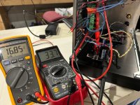
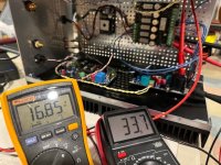
Well, um, was doing my homework, and found that I couldn't get a stable 70mA draw- the applied voltage to keep the defective Missouri board drawing 70mA had to be adjusted upwards every 30 seconds or so. Nothing was getting hot that I could feel. I kept chasing voltage readings across test points until suddenly the electrolytic filter capacitor C12, which had been installed backwards, popped. So there you have it.
With C12 replaced, the defective Missouri board draws about 10mA with the ICs out, and a little under 30mA with them in. Same for the other channel. With 36V in the top of R13/14 measures 27.55V which is a familiar reading from other cards.
Thank you Mark for the excellent troubleshooting guide.

With C12 replaced, the defective Missouri board draws about 10mA with the ICs out, and a little under 30mA with them in. Same for the other channel. With 36V in the top of R13/14 measures 27.55V which is a familiar reading from other cards.
Thank you Mark for the excellent troubleshooting guide.
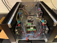
My Ship of Theseus is (finally) up and running with the Missouri front end. I have Dreadnaught boards completed but not yet adjusted. Bulwark boards are still in pieces in the kit box and Bon Homme Richard boards still in sealed bags from the PCB fab shop.
Looking back at this thread, I can’t believe I started this in 2022! I have had the boards completed for well over a year, but this project stalled when it came to putting it in a chassis. That problem was solved after I completed an XA-252 build where I cut two 5U chassis to make mono blocks, ending up with two 5U heatsinks for this project. I bought an extra inner base from Modushop and some aluminum from Amazon to form the basis for the chassis I show in the pictures. Top, bottom and faceplate will finish it off. Someday. But that’s not the important part of this project…
Mark - This thing sounds really good! It went together for me without issue. The output boards adjusted easily to half the source voltage with just a few twists of the RV1 trimpots. Thanks for such a terrific project!
Attachments
Congratulations @glenv6 !! With 5U heatsinks, you've got the coolest running 10 watt class A amplifier in your entire timezone! Maybe take 1.5 minutes to read this 2-line post, and ruminate.
@Mark Johnson I think I could use half of a 5U heatsink on each channel and still have enough cooling capacity, which I may do once the thrill of listening to this amp wears off a bit...
How did the Hornet FE do at Le Mans this weekend? 🤓
How did the Hornet FE do at Le Mans this weekend? 🤓
I have been listening to this amp with the balanced Missouri FE and my completely balanced pre (Doug Self designed) through my SBA-761s (Troels Gravesen) and I have to say this amp sounds like it pumps out significantly more than 10 watts. With the volume control anywhere past about a quarter of a turn, the music is blasting. And not an overdriven distorted blasting, but a clear well controlled and very musical blasting. Generally, the amp reproduces a full, rich bass. The midrange is coherent and nicely detailed, and the upper range is pleasing and open. My listening sessions included vinyl, CD and FLAC media, with music styles ranging from Lee Morgan (Sidewinder on Blue Note vinyl), to Hendrix (Live at Monterrey CD), Fleetwood Mac, Strauss, Tom Waits, Yo-Yo Ma, etc.
The Ship of Theseus compares favorably with the most detailed sounding amps in my collection.
The Ship of Theseus compares favorably with the most detailed sounding amps in my collection.
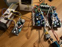
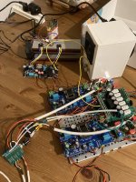
Just for info/sharing: here are pictures of a Ship of Theseus being prototyped with the Front End 2022.
Goal is to fit everything except MOS Channel on the chassis metallic plate. Mosfet boards will be on the heatsink of a 300m 3U.
It plays music!
Original goal was to have the Nimitz front end horizontal for easy access to the M2x input board. (Vertical on my M2x so, it is a bit troublesome to change quickly)
But i got carried away, thought it would be nice to have the Front End 2022 using the same power supply...
Now, i am discovering cables management is painful, balanced input don't help...
I have time to improve the wiring before i order the chassis.
Anyways, it is just as info if somebody had the same idea...
Attachments

- Home
- Amplifiers
- Pass Labs
- Ship Of Theseus: compatible, interchangeable amplifier modules