Coming back to this after quite a while, but in case it's useful for others.OK, VHALF is fine. A scope may take a little while to arrange as I'm out in Dubai currently, hopefully it's possible before I have to travel at the end of next week.
I couldn't easily manage a scope out in Dubai so ended up building up a new board and replacing parts bit by bit. It turned out it was the Edcor causing the issue which I switched for another one last night, that was the last thing I expected...
All works fine now and sounds excellent, thanks Mark
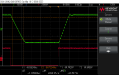
Speaking of old business, I had retested for this but didn't post. Managed only 39Vp-p before distress on this one, an earlier proto board, but got better than 25V/us on rise and fall slewing. No issues after 30 seconds.You know that YOU are going to run it with a 100 kHz, maximum amplitude square wave, for at least 30 seconds, during qualification testing. So you can take a scope photo of its lovely HF response at large amplitudes. And also to visually demonstrate the full 20 volts/microsecond slew rate capability of the OPA604 opamp chip.
Attachments
... replacing parts bit by bit. It turned out it was the Edcor causing the issue which I switched for another one last night, that was the last thing I expected...
Ooof! That's a surprise. Congratulations on discovering the root cause, condolences that it was the interstage transformer.

[Question on FQA36P15 possible replacement]
Hi.
The "Ship of Theseus" was build with "available MOSFET" in mind and i had a plan to build it because of the re-use of M2X daughter boards. Yet FQA36P15 seem now not to be available (or more than 1year lead time).
Some others threads are discussing FQA36P15 as possible remplacement, but is it OK for the Theseus amp ?
Link to those threads:
https://www.diyaudio.com/community/...approach-to-perfect-sound.374507/post-7259159
https://www.diyaudio.com/community/...approach-to-perfect-sound.374507/post-7261172
Or some others MOSFET might be used ?
My goal is to buy the devices in advance with orders for others things (i should have done so before ! )😏
...Answering my own post, after i learned a few things, and if helpful for others / increase one own's knowledge...
Different posts on the internet mentionned characteristics to compare but not specifically how.
In the end, this DigiKey forum was helpful https://forum.digikey.com/t/how-to-find-replacement-bjt-mosfet-and-igbt-transistors/7017 , i followed it for this search https://www.digikey.fr/fr/products/...FUhAXYAeVQAWVx0bAAVz4uHigK4ADV4gBbYRcBpNcRIoA
(hope it works), found the image attached.
FQA36P15 and the ones recommended in the other posts are shown. The advice in the forum helps choosing the right one
(don't know about audio difference though!)
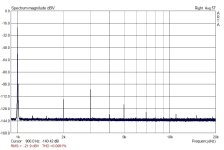
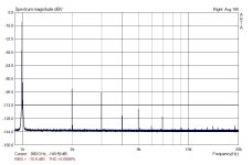
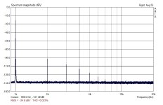
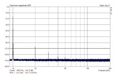
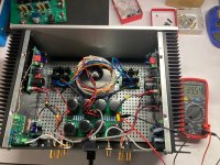
I finished building the Kitty Hawk. The ZTXs are not the ones ordered from Mouser as thy will arrive in May 2024. I bought them from a Chinese seller. I think they are original. These are the graphs showing the excellent behavior of the FE. Edcor's contribution to the THD is more than acceptable. I used a variable power supply set at 34V, the voltage measured on the SONY VFET OS2. Between the sound card and the FE I used Pete Millett's interface: http://www.pmillett.com/ATEST.htm
To measure the input/output voltage of the FE I used the ACrms voltmeter of the interface. Compared them with my BM235. The JFET of the FE is 2SK170.
These are the measured voltages:
First graph: Ving = 0.59V, Vout = 2.85V
Second graph: Ving = 2.09V, Vout = 10.07V
Third graph: Ving = 4.29V, Vout = 20.6V
Fourth graph ( no trafo ): Ving = Vout = 0.59V
Ffth graph ( no trafo ): Ving = Vout =2.09V
Attachments

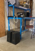
I sailed my Ship of Theseus from one port to another over the last couple days, the latter being a 4U Deluxe chassis and the former, a temporary hack in a monoblock chassis that I've shared pictures of before.
I'm using a frame mounted 36V Meanwell SMPS rather than a laptop brick, which allows for mounting inside the chassis and running off of mains voltage. The Meanwell doesn't have a ton of good mounting holes that match up with the Deluxe drill patterns, so I mounted it on it's edge off the base plate. It's fine. I'm also using the Pass Labs filter because it was gifted to me. It seems to drop 2V so the 36V of the SMPS becomes 34V at the boards, so I set the bias at the output Mosfet sources to 17V. I'm running Pequod boards with a dual op-amp at the moment.
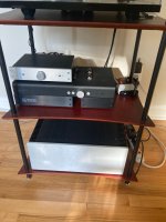
I've been playing a bass-prominent digital source and a weird unbal into an ACA lately in my garage workshop, so it was striking to me how much better the Ship of Theseus sounded- smooth, balanced across the frequency range, and detailed. Digital tracks with too much muddy bass or harsh treble came through clear even on mediocre speakers with a preamp intended to smooth them, and on my main system with a B1 buffer it sounds even smoother. There is zero, and I mean zero, hum on the speakers at any volume level, wired as shown.
This is a great amp. On my main system, it's replaced a P-channel Sony V-fet tonight, and the Theseus sounds fantastic.
I'm using a frame mounted 36V Meanwell SMPS rather than a laptop brick, which allows for mounting inside the chassis and running off of mains voltage. The Meanwell doesn't have a ton of good mounting holes that match up with the Deluxe drill patterns, so I mounted it on it's edge off the base plate. It's fine. I'm also using the Pass Labs filter because it was gifted to me. It seems to drop 2V so the 36V of the SMPS becomes 34V at the boards, so I set the bias at the output Mosfet sources to 17V. I'm running Pequod boards with a dual op-amp at the moment.
I've been playing a bass-prominent digital source and a weird unbal into an ACA lately in my garage workshop, so it was striking to me how much better the Ship of Theseus sounded- smooth, balanced across the frequency range, and detailed. Digital tracks with too much muddy bass or harsh treble came through clear even on mediocre speakers with a preamp intended to smooth them, and on my main system with a B1 buffer it sounds even smoother. There is zero, and I mean zero, hum on the speakers at any volume level, wired as shown.
This is a great amp. On my main system, it's replaced a P-channel Sony V-fet tonight, and the Theseus sounds fantastic.
Attachments
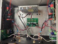
Good on ya, @ranshdow !! Nice build with plenty of room inside for both hands and multimeters.
The Pequod board might resemble a "starter home" in some ways: it's stout, good performing, and perfectly suited to first-Theseus-build needs. If some day you decide you want a breathtaking Malibu mansion, Hornet and Kitty Hawk are available. And good old 6L6 will remind you to never forget BHR too.
The Pequod board might resemble a "starter home" in some ways: it's stout, good performing, and perfectly suited to first-Theseus-build needs. If some day you decide you want a breathtaking Malibu mansion, Hornet and Kitty Hawk are available. And good old 6L6 will remind you to never forget BHR too.
I've been wondering already what input board to build next. I have some ~98% assembled Missouri boards but I've lost interested in balanced drive for now. I'll have to look into those others. Thanks guys!
There's also the IXTQ36P15 which by the specs (and pn, how funny) looks almost identical to the FQA36P15. It's also in stock at DigiKey....Answering my own post, after i learned a few things, and if helpful for others / increase one own's knowledge...
Different posts on the internet mentionned characteristics to compare but not specifically how.
In the end, this DigiKey forum was helpful https://forum.digikey.com/t/how-to-find-replacement-bjt-mosfet-and-igbt-transistors/7017 , i followed it for this search https://www.digikey.fr/fr/products/filter/transistors/fet-mosfet/fet-mosfet-simples/278?s=N4IgjCBcoGwJxVAYygMwIYBsDOBTANCAPZQDaIALGGABxwDsIAuoQA4AuUIAyuwE4BLAHYBzEAF9CMAAwxEIFJAw4CxMiADMNAKxhpG5m06Qe-YWMkgZNeYuV5CJSOTBwYFOBEKuaMDV5AAJjAKCmlAkEJAwPDQyKDA7Xok+MCNemSDKKoYPVTtGBgY1JhtYIiouDhtT3j6MALpeJp0mhsWEA4uXkFRCSkwCOgFNCwHNWcgmnoKGgqgzw0-VKr6GgCMpZsoooYAig0NaXomnaOQw07jU16LKNkbYa6TAFUhAXYAeVQAWVx0bAAVz4uHigK4ADV4gBbYRcBpNcRIoA
(hope it works), found the image attached.
FQA36P15 and the ones recommended in the other posts are shown. The advice in the forum helps choosing the right one
(don't know about audio difference though!)
View attachment 1169082
It's got a lower Vgs though, +/- 20V vs the +/- 30V of the FQA36P15. If one sets the source pin at +17V as I've done, and the gate swings to -3V as the gate drive circuit seems designed to go to -5V, it might release it's magic smoke? The IXTQ24P20 has the same Vgs spec. A fun $15 experiment? Idk.
There's also the IXTQ36P15 which by the specs (and pn, how funny) looks almost identical to the FQA36P15. It's also in stock at DigiKey.
[The IXTQ36P15] has got a lower Vgs [than the Theseus original FQA36P15}]though, +/- 20V vs the +/- 30V of the FQA36P15. If one sets the source pin at +17V as I've done, and the gate swings to -3V as the gate drive circuit seems designed to go to -5V, it might release it's magic smoke? The IXTQ24P20 has the same Vgs spec. A fun $15 experiment? Idk.
In the Theseus circuit, diode D4 prevents excessively high Vgs. When swinging the PMOSFET gate voltage from low to high, it can't go high forever. D4 forward biases and clamps the MOSFET Vgs to be no greater than +0.7V. {and of course a PMOS like this one, operating as a class A follower, never cuts off, thus Vgs never goes positive anyway}
When swinging the PMOSFET gate voltage from high to low, it can't go low forever. D4 enters the Zener/avalanche breakdown region, which clamps MOSFET Vgs to be no lower than -12 volts.
So in both cases, Vgs remains safely within the (-20 < Vgs < +20) limits. Thanks to little bitty D4. It's a hero.
_
Attachments

Some continued listening impressions.
Vinyl is hard. Or at least, it's easy to make it sound bad, at least to me. A ringy or hollow preamp, a narrow power amp, these kinds of things are more noticeable playing a record than a CD or a modern digital source. I've been listening to records through my Ship of Theseus pretty exclusively recently and it really does sound wonderful. It's a touch brighter and harder and a bit less full in bass than my P-channel lottery V-FET, but the sound is fascinating, so fascinating I haven't even rolled the op-amps in my Pequod front end cards yet. I woke up this morning with singer-songwriters in my head, and I've played Paul Simon's Graceland, Nick Drake's Pink Moon, and now Car Seat Headrest so far today. This really is a great amp, 10/10 recommend building one.
Vinyl is hard. Or at least, it's easy to make it sound bad, at least to me. A ringy or hollow preamp, a narrow power amp, these kinds of things are more noticeable playing a record than a CD or a modern digital source. I've been listening to records through my Ship of Theseus pretty exclusively recently and it really does sound wonderful. It's a touch brighter and harder and a bit less full in bass than my P-channel lottery V-FET, but the sound is fascinating, so fascinating I haven't even rolled the op-amps in my Pequod front end cards yet. I woke up this morning with singer-songwriters in my head, and I've played Paul Simon's Graceland, Nick Drake's Pink Moon, and now Car Seat Headrest so far today. This really is a great amp, 10/10 recommend building one.
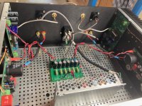
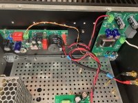
Some more of my nonsense, and a question. I want to try powering my Ship of Theseus with a linear power supply, to see what if any difference there is in the sound. I've had a half-plan to build a separate supply for this amp and others, but for now it seemed expedient to try it on the Theseus in situ using the roomy chassis I have, and some parts from another amp.
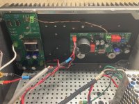
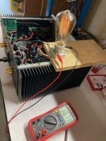
A clone of the First Watt F1 power supply, hooked up to a 300VA transformer with 28VAC secondaries, is shown below. Unloaded it produces 39.5V of rectified DC, which is 3.5V above the Ship of Theseus / Lottery VFET SMPS spec* of 36V. When one channel of this supply is loaded down with a 36 Ohm light bulb, the voltage across the bulb drops seven-tenths of a volt to 38.8V. Now, a Ship biased at 1.6A @ 36V represents a formal load of 22.5 Ohms, so I'd expect the voltage of this PSU feeding a Ship and it's front-end card to drop a tiny bit less than this under full load. Did I do that math right?
Is ~39V loaded rail still too high to power a Ship of Theseus and it's front-end cards? I really don't want to blow anything up. I'd rather hunt out a trafo with lower secondary voltage first, than blow anything up. I have yet to power my Ship directly with this linear supply, so there is still time to change course.
*note this spec is defined for the SMPS prior to any filtering boards. I wasn't going to include any of those SMPS filters with my linear supply implementation, which makes the rail voltage difference I describe above more severe than it would be if an SMPS was delivering that much over-voltage into a filtering board.
Attachments
Was thinking of a cap multiplier on each channel as I understand they can drop about three volts depending on the MOSFET. Another transformer is ~$60, and hitting the right secondary voltage seems to be guesswork. This one is 28V secondaries which by the 1.3:1 heuristic should have been 36.4V DC, instead I'm seeing a ratio of 1.4:1.
Measure the the actual secondary voltage. Anteks are rated for 115V mains, my mains run 123V -125V so the secondary winding real measured voltage is always higher than the spec sheets.
- Home
- Amplifiers
- Pass Labs
- Ship Of Theseus: compatible, interchangeable amplifier modules