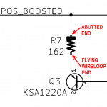
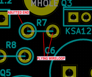
I'm afraid you misinterpreted the silkscreen guidelines, and installed every resistor backwards. See attached images of a different PCB whose name is not Missouri, but whose silkscreen guidelines are the same as the ones on Missouri. It seems that on your board, what I intended to be the flywire is actually the butt, and what I intended to be the butt is actually the flywire. Don't unsolder resistors and flip them; instead, adapt and improvise.
For your PCB it means that R11, R13, and R14's flywires are all connected to GND. That's why you measured 0.0 volts on those resistors' flywires.
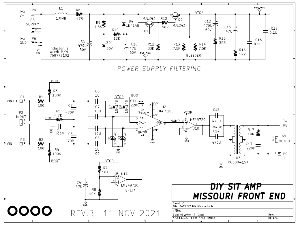
But the goal is to see whether the top half of your Missouri is correctly producing the filtered supply voltage called VTOP.
To get an accurate measurement of VTOP, connect voltmeter blackprobe to PSU GND and touch voltmeter redprobe to pin 7 of U2, and then to pin 8 of U1. Both are connected to VTOP and both should measure somewhere in the vicinity of +28 volts. If you installed diodes D2 and D5 in such a way that their CATHODES (band end) are probe-able, those cathodes are also connected to VTOP. Your voltmeter should read somewhere in the vicinity of +28 volts.
edit- For those who might whine about the flywire notation, remember that member @ElliotA built another Missouri board, presumably with all resistors backwards just like this board, and he believes the other Missouri works just fine. As indeed it should: resistors are symmetric components and it makes absolutely no difference electrically, which way they're stuffed and soldered.
The only disadvantage of stuffing the resistors backwards is: now you're going to have more difficulty making measurements, because important probe points on important signals are now going to be buried under the butt of vertical components. But hey, if you never make mistakes and never need to debug or measure your boards, then it doesn't matter whether signals are or aren't probe-able; you'll never probe then anyway! It's your board, build it however you please, and nobody can stop you.
_
For your PCB it means that R11, R13, and R14's flywires are all connected to GND. That's why you measured 0.0 volts on those resistors' flywires.
But the goal is to see whether the top half of your Missouri is correctly producing the filtered supply voltage called VTOP.
To get an accurate measurement of VTOP, connect voltmeter blackprobe to PSU GND and touch voltmeter redprobe to pin 7 of U2, and then to pin 8 of U1. Both are connected to VTOP and both should measure somewhere in the vicinity of +28 volts. If you installed diodes D2 and D5 in such a way that their CATHODES (band end) are probe-able, those cathodes are also connected to VTOP. Your voltmeter should read somewhere in the vicinity of +28 volts.
edit- For those who might whine about the flywire notation, remember that member @ElliotA built another Missouri board, presumably with all resistors backwards just like this board, and he believes the other Missouri works just fine. As indeed it should: resistors are symmetric components and it makes absolutely no difference electrically, which way they're stuffed and soldered.
The only disadvantage of stuffing the resistors backwards is: now you're going to have more difficulty making measurements, because important probe points on important signals are now going to be buried under the butt of vertical components. But hey, if you never make mistakes and never need to debug or measure your boards, then it doesn't matter whether signals are or aren't probe-able; you'll never probe then anyway! It's your board, build it however you please, and nobody can stop you.
_
Attachments
Last edited:
Thanks Mark, now you say it, it's there to see in plain sight. At least I was wrong in a consistent way...I'm afraid you misinterpreted the silkscreen guidelines, and installed every resistor backwards. See attached images of a different PCB whose name is not Missouri, but whose silkscreen guidelines are the same as the ones on Missouri. It seems that on your board, what I intended to be the flywire is actually the butt, and what I intended to be the butt is actually the flywire. Don't unsolder resistors and flip them; instead, adapt and improvise.
For your PCB it means that R11, R13, and R14's flywires are all connected to GND. That's why you measured 0.0 volts on those resistors' flywires.
But the goal is to see whether the top half of your Missouri is correctly producing the filtered supply voltage called VTOP.
To get an accurate measurement of VTOP, connect voltmeter blackprobe to PSU GND and touch voltmeter redprobe to pin 7 of U2, and then to pin 8 of U1. Both are connected to VTOP and both should measure somewhere in the vicinity of +28 volts. If you installed diodes D2 and D5 in such a way that their CATHODES (band end) are probe-able, those cathodes are also connected to VTOP. Your voltmeter should read somewhere in the vicinity of +28 volts.
edit- For those who might whine about the flywire notation, remember that member @ElliotA built another Missouri board, presumably with all resistors backwards just like this board, and he believes the other Missouri works just fine. As indeed it should: resistors are symmetric components and it makes absolutely no difference electrically, which way they're stuffed and soldered.
The only disadvantage of stuffing the resistors backwards is: now you're going to have more difficulty making measurements, because important probe points on important signals are now going to be buried under the butt of vertical components. But hey, if you never make mistakes and never need to debug or measure your boards, then it doesn't matter whether signals are or aren't probe-able; you'll never probe then anyway! It's your board, build it however you please, and nobody can stop you.
_
I do then measure circa 28-29v on R11, R13, and R14. Also U1, U2, D2 and D5. Is it fair to say then that from a power perspective the board is behaving OK?
VTOP seems to be working correctly, yes.
A quick next test would be to put a tiny drop of nail polish on each of the two ICs on your other (working) Missouri. Put a big adhesive tape label "POOPY" on the bottom of the nonworking Missouri. Then swap chips between the two Missouri boards.
Non working Missouri gets the nail polish (known good) ICs. Working Missouri gets the no nail polish (as yet unproven) ICs. Consult the schematic, make sure you plug the LME chips where they belong. Make sure you plug the THAT chips where they belong.
Play music through each of them.
Is the formerly non working (POOPY) board still dead? Is the formerly working board (no bottom label) still alive? If yes and yes, that means all four ICs are good and the problem is definitely on the POOPY board.
Is the formerly non working (POOPY) board now alive? Is the formerly working board (no bottom label) now dead? If yes and yes, that means one or both of the ICs without nail polish is bad, AND it also means the rest of the POOPY board is good.
OK, I switched the ICs separately and then all together for good measure. I can confirm that POOPY board is where the poopy is and the ICs themselves are fine. For what it's worth when I switched the negative wires to the speakers at the connectors the quiet side flipped, I don't know if that helps narrow things down Mark.
By the way, if anyone wants Missouri boards, I do have some spare which could go to good homes.
By the way, if anyone wants Missouri boards, I do have some spare which could go to good homes.
Sounds like you may also have a problem with speakers themselves, speaker cables, speaker connectors on your back panel, or chassis internal wiring between your amp channel boards and the back panel speaker connectors.
With power off and disconnected, use ohmmeter to verify continuity between the two black speaker terminals. Do this where the speaker cables plug in (OUTSIDE the chassis), not at the solder joints inside the chassis. Repeat for the two red speaker terminals OUTSIDE. One color should have continuity, the other color not. You may have to switch to ohms mode instead of continuity mode to get a more solid reading.
Swap the speakers, verify they both play.
Swap the speaker cables, verify they both play.
Swap the amp channel cards, verify they both play..
.
.
.
.
.
which has nothing to do with the Front End cards at allwhen I switched the negative wires to the speakers at the connectors the quiet side flipped
Last edited:
And if there is continuity between red speaker posts but no continuity between black speaker posts ...
Then the amp channels are using the red speaker posts as "common" while they drive the black speaker posts independently. Swapping the speaker wires on the black posts, is equivalent to unplugging both 2wire cables completely and then swapping them. If left speaker was dead before the swap, then right speaker is dead after the swap.
--IF-- there is continuity between red speaker posts but no continuity between black speaker posts then you can disregard post #145. Nothing's wrong downstream.
Ah thanks Mark, yes, this is the case - there is continuity on the red but not the black posts. I guess it's not possible to do similar on the positive and ground signal connections because of the transformer, I get continuity from XLR to FE input and from FE outputs to the output stage inputs,And if there is continuity between red speaker posts but no continuity between black speaker posts ...
Then the amp channels are using the red speaker posts as "common" while they drive the black speaker posts independently. Swapping the speaker wires on the black posts, is equivalent to unplugging both 2wire cables completely and then swapping them. If left speaker was dead before the swap, then right speaker is dead after the swap.
--IF-- there is continuity between red speaker posts but no continuity between black speaker posts then you can disregard post #145. Nothing's wrong downstream.
OK, VHALF is fine. A scope may take a little while to arrange as I'm out in Dubai currently, hopefully it's possible before I have to travel at the end of next week.Now you can perform the remaining suggestions in post #135 starting with VHALF, then the signal gen + scope tests.
Hi Mark. Thank you for these projects. I'm starting on the Missouri and I was wondering if you or someone else can go through the calculations for the input resistor power recommendation. The BOM says 100R, 0.6W for R1 & R2
I tend to use 0.6W 1% metal film resistors frequently, almost as often as possible. 0.6 Watt parts are usually easier to find in stock (because most other projects call for 0.25W or 0.5W resistors), they're the same physical size, and they aren't much more expensive. Bigger safety margin, less hassles with backorders, what's not to like?
In the Missouri front end card, 100 ohm resistors R1 and R2 turn out to dissipate very VERY little power, so in those cases there is no danger if someone uses 0.125 watt resistors in those positions. But that's not how I built MY Missouri cards -- I used 0.6 Watt 100 ohm resistors. I pulled them from my bag of 100 pieces of 100 ohm 0.6 Watt resistors that I bought at Mouser several years ago.
In the Missouri front end card, 100 ohm resistors R1 and R2 turn out to dissipate very VERY little power, so in those cases there is no danger if someone uses 0.125 watt resistors in those positions. But that's not how I built MY Missouri cards -- I used 0.6 Watt 100 ohm resistors. I pulled them from my bag of 100 pieces of 100 ohm 0.6 Watt resistors that I bought at Mouser several years ago.
Thank you for that explaination. Nothing wrong with a larger safety margin. I was just wondering if I had missed something
Getting to play with the Theseus MOS output stage, currently driven by the Pequod input stage. Power from an open frame 36V MeanWell filtered by Theseus-PSFILT SMPS filter and power on/off de-thumper.
Although I've only listened so far for a few hours, this sounds truly excellent! I’m very pleased with this project as a whole, the possibilities are almost unlimited for tinkering and trying a large amount of different circuit topologies and other neat things.
😎


Although I've only listened so far for a few hours, this sounds truly excellent! I’m very pleased with this project as a whole, the possibilities are almost unlimited for tinkering and trying a large amount of different circuit topologies and other neat things.
😎
Last edited:

A lovely build, congratulations! Quite roomy inside that chassis, even with the PSU on the inside.
The power output stage is nice and compact since there's no thick aluminum T-bar extrusion for TO-3 mounting.
And kudos for using Pass Labs axial film capacitors on the inputs. Much envy, much covet.
Viewer challenge: find the SOIC-to-DIP adapter in the photos. Member 6L6 has chosen to install a super modern, super high-spec opamp that is not sold in thru hole packaging. Billowing clouds of testosterone rise from his Pequod boards!
Last edited:
The input wires are stripped from a CAT6 cable and conveniently already twisted. 🙂
That opamp happens to be the absolutely excellent LME49720 on an old SparkFun SOIC-DIP adaptor. A wonderful sounding opamp designed for the highest performance audio from National’s Bob Pease era. (EDIT: the photo was taken with a OPA1642, for the eagle-eyed people who can tell the TI markings... 😉 )
That opamp happens to be the absolutely excellent LME49720 on an old SparkFun SOIC-DIP adaptor. A wonderful sounding opamp designed for the highest performance audio from National’s Bob Pease era. (EDIT: the photo was taken with a OPA1642, for the eagle-eyed people who can tell the TI markings... 😉 )
Last edited:
Pics of my Nimitz card build. My plan is to modify my P VFET lottery build with the Tuba filter and the Nimitz FE.
Reasoning is I really like my M2x with Norwood and I want to see how it sounds with the VFET.
Can somebody point me in the direction of how to best test the Nimitz FE card. I am struggling to find something. It needs to work properly before being installed. Thanks,
Don
Reasoning is I really like my M2x with Norwood and I want to see how it sounds with the VFET.
Can somebody point me in the direction of how to best test the Nimitz FE card. I am struggling to find something. It needs to work properly before being installed. Thanks,
Don
Jim, I would just like to confirm the pics are of a 4U 300 UMS chassis. Thanks,Getting to play with the Theseus MOS output stage, currently driven by the Pequod input stage. Power from an open frame 36V MeanWell filtered by Theseus-PSFILT SMPS filter and power on/off de-thumper.
Although I've only listened so far for a few hours, this sounds truly excellent! I’m very pleased with this project as a whole, the possibilities are almost unlimited for tinkering and trying a large amount of different circuit topologies and other neat things.
😎
View attachment 1082782View attachment 1082783View attachment 1082784
Don
That is correct. 4U 300mm Deluxe. 🙂
That particular one is an older example, but the important bits are all the same.
That particular one is an older example, but the important bits are all the same.
A general plan of attack when testing and troubleshooting a Front End card for Theseus, is laid out in post #135. Only twenty five posts ago.
If you're worried about your unproven Nimitz destroying your precious Norwood daughterboards, stuff and solder your Tucson boards and use dirt cheap opamps (I suggest TL071 which is plentiful and costs less than $1). Give Nimitz a chance to wreck your Tucson boards -- they are expendable. If it doesn't, leave Tucson in the amplifier for a week or two just in case trouble manifests itself gradually. Finally when you've got plenty of confidence in Nimitz, swap Tucson out and swap Norwood in. Done.
If you're worried about your unproven Nimitz destroying your precious Norwood daughterboards, stuff and solder your Tucson boards and use dirt cheap opamps (I suggest TL071 which is plentiful and costs less than $1). Give Nimitz a chance to wreck your Tucson boards -- they are expendable. If it doesn't, leave Tucson in the amplifier for a week or two just in case trouble manifests itself gradually. Finally when you've got plenty of confidence in Nimitz, swap Tucson out and swap Norwood in. Done.
- Home
- Amplifiers
- Pass Labs
- Ship Of Theseus: compatible, interchangeable amplifier modules