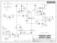
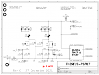
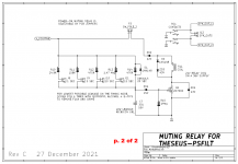
This Ship Of Theseus project extends the limited-edition diyAudio VFET amp kits, by introducing several new circuit modules which are compatible and interchangeable with the modules in the original kits. At this writing, the Ship Of Theseus includes seven new Front End cards, a new PSU filter card (with turnoff thump suppression), and a new output stage card which uses active-production MOSFETs instead of rare and obsolete VFET transistors.
Owners of an original VFET kit can experiment with different Front Ends to customize their amplifier, and tailor it to their own sonic preference. They also can drop in the new PSU filter card, to enjoy its turnon/turnoff thump reduction and improved 120 Hz filtering.
Builders without an original VFET kit will need Front End cards, a PSU filter card, and output stage cards. The Ship Of Theseus portfolio of choices, provides several possibilities.
I've collected together all of the circuit design information into one (big) .pdf file, attached below. It includes the schematics of each board, and my circuit description of each.
There is also a .zip archive attached here to post #1, containing everything. All Detailed Parts Lists, all Gerber files for PCB manufacturing, and all schematics. All Ship Of Theseus cards and all Ship Of Theseus files are contained in this one single .zip archive.
For ease of browsing here on the diyAudio discussion Forum, I will also be posting images of the schematics here, in posts #2 and #3.
As updates and bug fixes occur, I'll make note of them here at the bottom of post #1.
_
Owners of an original VFET kit can experiment with different Front Ends to customize their amplifier, and tailor it to their own sonic preference. They also can drop in the new PSU filter card, to enjoy its turnon/turnoff thump reduction and improved 120 Hz filtering.
Builders without an original VFET kit will need Front End cards, a PSU filter card, and output stage cards. The Ship Of Theseus portfolio of choices, provides several possibilities.
I've collected together all of the circuit design information into one (big) .pdf file, attached below. It includes the schematics of each board, and my circuit description of each.
There is also a .zip archive attached here to post #1, containing everything. All Detailed Parts Lists, all Gerber files for PCB manufacturing, and all schematics. All Ship Of Theseus cards and all Ship Of Theseus files are contained in this one single .zip archive.
For ease of browsing here on the diyAudio discussion Forum, I will also be posting images of the schematics here, in posts #2 and #3.
As updates and bug fixes occur, I'll make note of them here at the bottom of post #1.
- Ship Of Theseus is electrically compatible with the VFET kits that the Store shipped in June-August 2021. All of these amplifiers use the exact same +36VDC switch mode power supply in "brick" format. It is Mean Well part number GST160A36-R7B and is sold by several distributors, including the diyAudio Store (link to sales page). It has an unusual DIN-4 plug; the corresponding jack mounted to the chassis rear panel is Mouser part number 806-KPJX-PM-4S (all plastic) and/or 806-KPJX-PM-4S-S (metal face). The original VFET chassis used the all plastic version, I believe.
- Nelson Pass's technical paper about the diyAudio Store Pchannel VFET amp, including parts list and internal wiring diagram, is (here)
- Nelson Pass's technical paper about the diyAudio Store Nchannel VFET amp, is found at this (link)
- There was a problem in the schematic and Detailed Parts List for MOS amp channel A and amp channel B, regarding the value of a single resistor (R5). I have updated the schematics and Detailed Parts Lists for the two Amp Channels; they are attached to post #60 of this thread -- 2022 , 13 March
_
Attachments
-
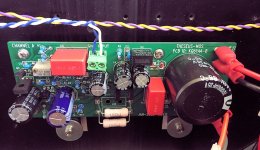
 topview.JPG240.3 KB · Views: 1,805
 -
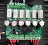
 chan_A.JPG208.3 KB · Views: 1,558
 -
 chan_B.JPG164.2 KB · Views: 1,531
 -
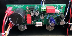
 PSFILT_1.JPG316 KB · Views: 2,505
 -
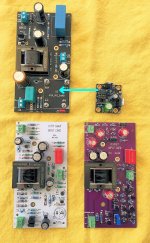 boards_NKH.JPG285.2 KB · Views: 1,693
 -
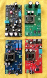 boards_LPMB.JPG267.5 KB · Views: 1,772
 -
Ship_of_Theseus_rev_2022_03_02.pdf685.7 KB · Views: 1,176
-
Theseus_Everything_2022_03_02.zip1.2 MB · Views: 911
Last edited:

Here are brief summaries of the seven new Front End cards. The previous Front Ends were named for British warships: Scourge, Bulwark, Marauder, and Dreadnought. The new Front Ends are named for American warships. Well, six of them are. The seventh, Pequod, is American but not a warship. It's the boat in Moby Dick.
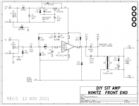
Nimitz is a customizable Front End which accepts M2x daughter cards. Builders can bolt whichever M2x card they wish into Nimitz, and that
becomes the Front End for a VFET or Theseus amplifier.
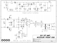
Missouri is a Front End that accepts balanced inputs. It uses the highly regarded THAT-1200 differential receiver IC for maximum CMRR
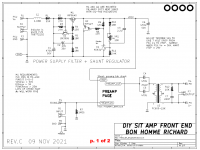
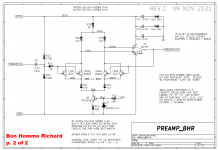
Bon Homme Richard is a high performance opamp (AD797), plus a discrete JFET input stage, fed by a shunt-mode voltage regulator for maximum PSRR
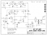
Kitty Hawk is a transconductance (current output) amplifier, which uses a Rush Cascode input stage: PNP follower + NJFET common gate.
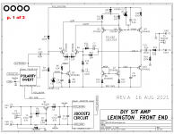
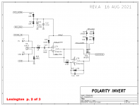
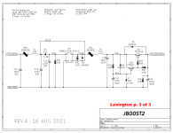
Lexington is a folded cascode discrete opamp, using a self-generated high voltage supply (“JBOOST2”) and no Edcor transformer. The boost circuit includes an isolated DC-to-DC converter module plus extensive filtering.
Hornet is a discrete opamp whose unusual all-JFET output stage has no degeneration resistors. The supply filter is cascoded, each of the two constant current sources are cascoded, and the input is a Rush Cascode.
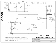
Pequod is a simple opamp follower with few parts and relatively modest parts cost. It accepts either dual opamps (e.g. LM4562) or single opamps (e.g. LT1122) and the two opamp sockets are surrounded by blank empty zones, making it easier to fit discrete opamp modules such as Sparkos or Burson, if desired.
_
Nimitz is a customizable Front End which accepts M2x daughter cards. Builders can bolt whichever M2x card they wish into Nimitz, and that
becomes the Front End for a VFET or Theseus amplifier.
Missouri is a Front End that accepts balanced inputs. It uses the highly regarded THAT-1200 differential receiver IC for maximum CMRR
Bon Homme Richard is a high performance opamp (AD797), plus a discrete JFET input stage, fed by a shunt-mode voltage regulator for maximum PSRR
Kitty Hawk is a transconductance (current output) amplifier, which uses a Rush Cascode input stage: PNP follower + NJFET common gate.
Lexington is a folded cascode discrete opamp, using a self-generated high voltage supply (“JBOOST2”) and no Edcor transformer. The boost circuit includes an isolated DC-to-DC converter module plus extensive filtering.
Hornet is a discrete opamp whose unusual all-JFET output stage has no degeneration resistors. The supply filter is cascoded, each of the two constant current sources are cascoded, and the input is a Rush Cascode.
Pequod is a simple opamp follower with few parts and relatively modest parts cost. It accepts either dual opamps (e.g. LM4562) or single opamps (e.g. LT1122) and the two opamp sockets are surrounded by blank empty zones, making it easier to fit discrete opamp modules such as Sparkos or Burson, if desired.
_
Attachments

Last edited:
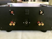
The rest of the schematics. And also a photo of the rear panel, showing the Neutrik RCA jacks used. These can be swapped out and replaced by XLRs in the same panel cutout, for use with Balanced inputs / Missouri.
_
_
Attachments

At least one!!Need to order another chassis. 🤣
There are lots of smaller profile chassis that could work with this assuming it has suitable heatsink area. You could power with a brick or with a metal-frame PSU inside the chassis. The possibilities are endless.
Hi Mark,
Wow, what a gift to this community. Thank you. The possibilities really have my head spinning.
I have a question about the circuitry surrounding the Edcor transformer. (This is a parenthetical as I recently implemented a pair of 1:2 Edcor's between my preamp and amp as an experiment). It looks like in nearly every case there is a pair of parallel capacitors on the primary (to block DC?) and what looks like a snubber circuit on the secondary. Is this what those are? Could you point me to a reference to help me better understand the design and application of DC blocking and snubbers on line-level transformers? I have a Quasimodo board on the way so if that's what was used here, that would be helpful to know.
The capacitors on the primary are, as you surmise, to block DC from the transformer. Remember that these amplifiers (the Vfet variations, if you will) are single-rail, and in order to make AC on the output (because music is AC) you need to have the ability for the amplifier circuit to raise and lower the voltage in DC to make the signal.
To this end, the amplifier has to live somewhere at about 1/2 the DC rail voltage at idle, so it can modulate the PSU both up and down (the peaks and valleys of the waves) and make AC. So the amplifier will be making around 18VDC at the output with zero signal. The coupling cap(s) block this DC from the output.
As for the snubber on the secondary, (something Nelson figured out with the Edcor used in this project) that’s mostly to help properly load the primary, and to tame a resonance in the transformer itself. This will vary amongst transformer design. Mark may be able to better explain than I.
Last edited:
The Zobel network across the transformer secondary, damps out a resonant peak in the transformer's frequency response. Nelson Pass said so (here) and I'll see if I can find where Bill Whitlock says the same thing about Jensen transformers.
There it is, in Bill's chapter "Audio Transformers" of the book Handbook For Sound Engineers, edited by Glen M. Ballou
_
There it is, in Bill's chapter "Audio Transformers" of the book Handbook For Sound Engineers, edited by Glen M. Ballou
_
Attachments
Last edited:
Thanks 6L6! I'm guessing both the input and output amplification stages inject DC into the AC audio signal, hence the need to avoid transformer core saturation from the input stage DC here.To this end, the amplifier has to live somewhere at about 1/2 the DC rail voltage at idle, so it can modulate the PSU both up and down (the peaks and valleys of the waves) and make AC. So the amplifier will be making around 18VDC at the output with zero signal. The coupling cap(s) block this DC from the output.
Thanks Mark! I didn't know that was also called a Zobel network. Bob Cordell's "Designing Audio Power Amplifiers", of which I have a copy, seems to discuss them in multiple places. That will get me started.The Zobel network across the transformer secondary, damps out a resonant peak in the transformer's frequency response. Nelson Pass said so (here) and I'll see if I can find where Bill Whitlock says the same thing about Jensen transformers.
There it is, in Bill's chapter "Audio Transformers" of the book Handbook For Sound Engineers, edited by Glen M. Ballou
_
I had done a quick 'reflected impedance' calculation for the 10k resistor alone and I got a value of 6.25Mohm on the primary, which wasn't making sense to me.
All of the above by Mark and 6L6 is correct.
The thing to look at is the value of the AC coupling caps (C11 and C12). 1000 uF is much larger than required to achieve full bandwidth into the output stage. It is certainly Ok to use that value, but a single 220 uF Elna Silmic + 0.47 uF Polypropylene film is worth listening to.
Or even a 100 uF Nichicon ES series + 1.0 uF Polycarbonate if you can get one. Lots of options are fun.
I‘ve tried these combos and prefer them to more generic bipolar caps.
Bravo Mark!
Lots of good bits and pieces here to mix and match. Thanks for sharing the Gerbers 😉
Lots of good bits and pieces here to mix and match. Thanks for sharing the Gerbers 😉
Once again, I am awestruck by the generosity of this community. I still summarize my personal experiences as playing with "Audio Legos". The modular nature of so many recent offerings allows me to plug-and-play / mix and match. My own fun comes from the listening pleasure of a good tune or two with gear that I've built. Perhaps one day, I can say I've even 'designed' something. However, making some small attempt to understand how varying topologies align with my preferences, and then attempting to sort out how my preferences might align with some measurements is great fun. The explanations regarding the overall topologies are extraordinarily valuable for me. Otherwise, it may as well be "magic".
Many thanks @Mark Johnson for more Legos to play with and the continued support. Note - It's not forgotten that I'm woefully behind on my promised M2x IPSs. Thus, the Nimitz may be a wonderful first choice, once I set aside some bench time.
Many thanks @Mark Johnson for more Legos to play with and the continued support. Note - It's not forgotten that I'm woefully behind on my promised M2x IPSs. Thus, the Nimitz may be a wonderful first choice, once I set aside some bench time.
Hi Mark,
You have certainly been busy with all of these alternatives, and a big thanks to you for the work, all the files and documentation - well done.
One quick question, for the output board and all different input modules - is the VCC supply +24Vdc across all products?
You have certainly been busy with all of these alternatives, and a big thanks to you for the work, all the files and documentation - well done.
One quick question, for the output board and all different input modules - is the VCC supply +24Vdc across all products?
Thanks to Mark and this wonderful community for more food for thought in audio amplifiers, and more potential drain on the "discretionary income" home budget!
GaryS - These amplifier modules are all swappable with the recent Sony Vfet project, which uses a +36vdc power supply.
Vcc = +36vdc
Vcc = +36vdc
Thank you Mark, amazing contribution.
Since the M2x I’ve had the idea of using a PCIe or M.2 connectors to make the cards truly plug and play. I’m sure something like this has already been done around here, any comments on how well this might work?
Since the M2x I’ve had the idea of using a PCIe or M.2 connectors to make the cards truly plug and play. I’m sure something like this has already been done around here, any comments on how well this might work?
- Home
- Amplifiers
- Pass Labs
- Ship Of Theseus: compatible, interchangeable amplifier modules