Rudy,
The board can accommodate PI or series s/pdif divider.
R60, R48, R49 are part of PI divider.
R48 and R49 are part of series divider.
R48 = 300Ω series resistance
R49 = 100Ω resistance to ground (shunt)
Modified BOM to reflect correct resistor number.
Regards,
Tibi
The board can accommodate PI or series s/pdif divider.
R60, R48, R49 are part of PI divider.
R48 and R49 are part of series divider.
R48 = 300Ω series resistance
R49 = 100Ω resistance to ground (shunt)
Modified BOM to reflect correct resistor number.
Regards,
Tibi
Last edited by a moderator:
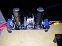
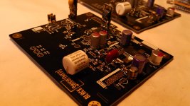
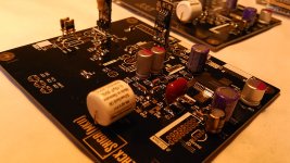
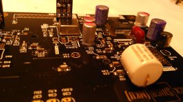
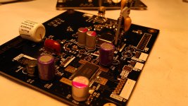
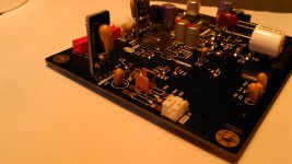
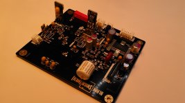
The new resistors are soldered now and that was an improvement.
Series resistance:270R/ 0.4 Watt, Vishay VAR-Series "naked" Z-Foil Resistor.
Shunt resistance:100R CADDOCK / 0.75 (3/4) Watt, MK-132 Series, 1%, Radial Lead, Precision Metal Film.
And the capacitors changed from the power supply that are now 2 x 1000uF Blackgate STD.
After the diodes, 1 x black gate 4,7uF n series (under the board) parallel to Blackgate 1000uF.
Now spending a week listening to music and after a week compare if something is changed from the sound.
Do not tell exactly what the differences are with my existing Shigaclone, be patient🙂
To be continued.
Regards,
Rudy
Attachments
I may suggest to remove that 4.7uF together with C62 100nF MKP and put a 100nF PIO.
I got degraded results paralleling/decoupling BlackGates with any capacitor, except PIO.
Also remove C66 and insert a small 10nF PIO as well.
Regards,
Tibi
I got degraded results paralleling/decoupling BlackGates with any capacitor, except PIO.
Also remove C66 and insert a small 10nF PIO as well.
Regards,
Tibi
The new resistors are soldered now and that was an improvement.
Series resistance:270R/ 0.4 Watt, Vishay VAR-Series "naked" Z-Foil Resistor.
Shunt resistance:100R CADDOCK / 0.75 (3/4) Watt, MK-132 Series, 1%, Radial Lead, Precision Metal Film.
270R and 100R will give an attenuation of about 11.3dB which is about a db less than the standard values used so far.
Of course how close to 0.5V your signal has to be and how big the perceived benefit is going to be, is a matter of DAC, so your sound benefit mileage may vary. The benefit of the below stuff for me was big.
My scope measurements (at the DAC's input after a 1.5m cable) were that we need about 14.2 dBs to get to the specified 0.5V peak to peak on the output
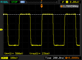
My choice was a T pad (50 series, 32 shunt, 50 series) for 75R input-75R output configuration (which I chose when I was wiring my own resistors. The smaller values of the Tee pad meant less wire used). With solid resistors, a Pi pad would be more suitable, because of less components in series with the signal (something like 111R-185R-111R). I have not tested the difference between L pad and symmetrical tee/pi pads directly. My choice for symmetrical impedance in the attenuator was based on the elimination of impedance change points, to minimize reflections. For the same reason I have also eliminated the RCA plug/socket, soldering the cable right to the attenuator.
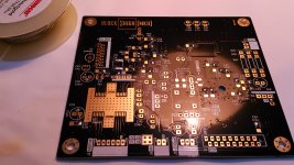
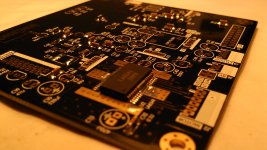
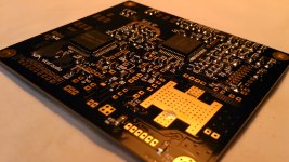
building shiga mkII high-grade
Going further with high-grade version of Shiga MKII.
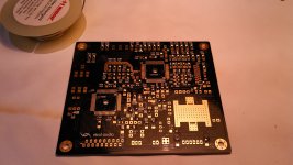
Preparing board for soldering.
Place a small drop of solder on each smd pad. So you'll solder one side of each component first.
Depending on which hand you use, place this solder drop on the right or left side of the component which was drawn on the PCB.
Regards,
Tibi
Going further with high-grade version of Shiga MKII.
Preparing board for soldering.
Place a small drop of solder on each smd pad. So you'll solder one side of each component first.
Depending on which hand you use, place this solder drop on the right or left side of the component which was drawn on the PCB.
Regards,
Tibi
Attachments
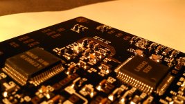
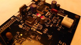
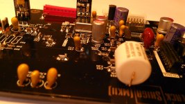
Best way to solder smd capacitors, especially large or high value ones, is to have them perpendicularly mounted, rotated at 90 degrees.
This dramatically reduce piezoelectric effect due any vibrations induced by music program and mechanic resonance. Another benefit is that any parasitic capacitance between capacitor layers and PCB traces are also minimized.
Even resistors have similar ceramic substrate (mainly on thin film resistors) and these do not exhibit same magnitude of piezoelectric effects, I decided to mount few of them vertically as well (in critical places) in order to minimize any parasitic capacitance with pcb traces.
I know it is harder to solder smd this way, but worth the effort.
This type of soldering can be done only manually. Stencil will not work.
Regards,
Tibi
Attachments
Last edited by a moderator:
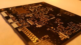
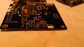
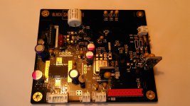
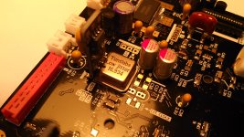
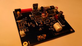
Please note that in above pictures L5 and L9 are not mounted. This need to be removed when miniregs are in place.
Also note that L8-ferrite bead, C59-10nF, R47-47ohm need to be mounted for Tentlabs XO.
Also C57 and C58 will not be mounted. These are needed only when internal LC78601R oscillator is used.
Regards,
Tibi
Also note that L8-ferrite bead, C59-10nF, R47-47ohm need to be mounted for Tentlabs XO.
Also C57 and C58 will not be mounted. These are needed only when internal LC78601R oscillator is used.
Regards,
Tibi
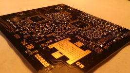
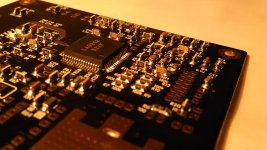
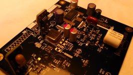
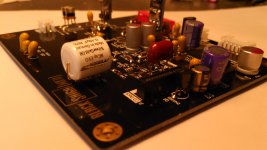
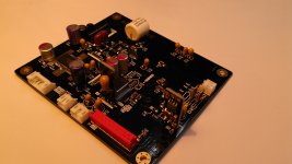
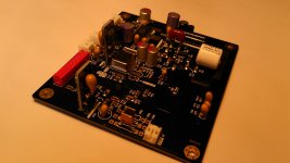
Solder IC's and smd transistor after all passive SMD parts are in place.
This is how the board should like after all smd parts are in place.
Estimated working time 3-4 h, including parts measurement and board cleaning.
Regards,
Tibi
This is how the board should like after all smd parts are in place.
Estimated working time 3-4 h, including parts measurement and board cleaning.
Regards,
Tibi
Attachments
I must mention that following high-grade parts are my personal choice and I selected these parts after several hundred hours of listening and comparisons.
Using different parts you can get better results or better profiled on your sonic preferences.
My preferred low jitter XO
- Tentlabs XO 16,9344MHz TentlabsShop
For highly commented C8, my choice is:
- C8 - Mundorf Silver-Goild OIL 0.1uF Mundorf Film Caps EVO - Silver|Gold + Oil
Please note that lowering the value of this capacitor may lead to oscillations and instability - tracking loss. I suggest do not go under 33nF. Personally I'll stay on the safe part and use 100nF.
C10 is decoupling laser CCS. A high current low ESR capacitor is mandatory. In this regard oscon/polymer/tantalum are best here.
C43 is the capacitor after internal LA6541+2SB764 regulator. This ensure regulator stability and noise is in direct relation with the ESR of this capacitor as well.
- C10 and C43 Sanyo OSCON 270uF Capacitors_Electrolytic_Sany😵scon
C19 is part of laser CCS. The quality of this cap will highly affect laser operation. Laser current is in relation with voltage across this capacitor. Use the best you can here. BG/oscon/tantalum. My choice BG PK 47uF - still available at partsconnex.
- C19 - Rubicon BlackGate PK 47uF Blackgate Electrolytic Capacitors PK Series
C20 and C23 are part of 2.5V reference. You may have noticed that on all Shiga's these capacitors are polymer in my kits.
The temperature stability of polymer caps recommend these here. The internal structure of LA9242M is in such way constructed that any leakage and internal series resistance of these capacitors will affect 2.5V reference.
My choice for R48 and R49 is Vishay naked.
IMHO the best resistors your money can buy for this application. Exceptional stability, tolerance and noise figures.
These will enhance resolution to dream level. I simply love these parts. 🙂
Vishay VAR-Series "naked" Z-FOIL RESISTOR
Miniregs - You have construction of these in this thread.
The icing on the cake is C11. Give it a try and be amazed.
Use a 1nF - 2n2F silver mica cap.
capacitor_film_smica.html
Regards,
Tibi
Attachments
-
 20140515_008.jpg691.3 KB · Views: 553
 -
 20140515_007.jpg775.4 KB · Views: 407
 -
 20140515_006.jpg530.6 KB · Views: 411
 -
 20140515_005.jpg651.2 KB · Views: 479
 -
 20140515_004.jpg805.5 KB · Views: 595
 -
 20140515_003.jpg617 KB · Views: 552
 -
 20140515_002.jpg642.8 KB · Views: 572
 -
 20140515_001.jpg801.3 KB · Views: 639
Last edited by a moderator:
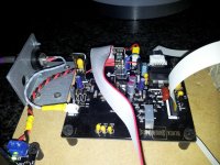
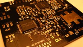
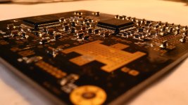
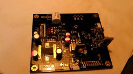
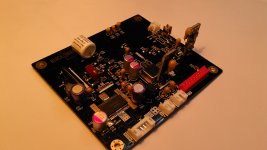
All parts mounted and board is almost ready to be connected to display and control board.
Take care on J1. A version of this connector can be mounted in two different ways. Zoom and follow below picture.
TBC.
Regards,
Tibi
Take care on J1. A version of this connector can be mounted in two different ways. Zoom and follow below picture.
TBC.
Regards,
Tibi
Attachments
-
 20140515_023.jpg841.6 KB · Views: 515
 -
 20140515_020.jpg642.7 KB · Views: 466
 -
 20140515_019.jpg493.6 KB · Views: 331
 -
 20140515_018.jpg489.5 KB · Views: 360
 -
 20140515_017.jpg763.6 KB · Views: 377
 -
 20140515_016.jpg705.6 KB · Views: 1,378
 -
 20140515_015.jpg715 KB · Views: 1,456
 -
 20140515_014.jpg750.7 KB · Views: 1,545
 -
 20140515_013.jpg533.1 KB · Views: 1,644
 -
 20140515_012.jpg663.5 KB · Views: 1,774
Last edited by a moderator:
+1 for C11
But I do not consider it icing 🙂 I consider it a significant part of the main course. It makes a huge difference. Possibly as big as C8.
Oh and moving from a cheap 1euro noname cap to a Cornell Dubilier also had a quite audible impact.
I hope to try the miniregs very soon. I will post back...
But I do not consider it icing 🙂 I consider it a significant part of the main course. It makes a huge difference. Possibly as big as C8.
Oh and moving from a cheap 1euro noname cap to a Cornell Dubilier also had a quite audible impact.
I hope to try the miniregs very soon. I will post back...
Yep, that is the famous C8. Standard is 0.1uF tantalum.
In picture I used an Arcotronics.
In the high-grade version I use Mundorf silver-gold-oil.
I saw some people used Duelund cast. 🙂
10uF tantalum are even better.
Regards,
Tibi
Tibi,
Has anyone tried a copper V-Cap in this position? If so, to what results? Thank You.
Tony G
Tibi,
Has anyone tried a copper V-Cap in this position? If so, to what results? Thank You.
Tony G
To my knowledge, V-Cap TFT is Peter's choice.
Tibi,
Has anyone tried a copper V-Cap in this position? If so, to what results? Thank You.
Tony G
I have a huge list of caps tested, but not V-Cap. I have used V-Cap in my Quasar amp and is a great capacitor.
Regards,
Tibi
Tibi, for 5v fixed minireg, we need 2 0R resistors or just one? Thanks.
Only one 0ohm resistor.
Regards,
Tibi
I may suggest to remove that 4.7uF together with C62 100nF MKP and put a 100nF PIO.
I got degraded results paralleling/decoupling BlackGates with any capacitor, except PIO.
Also remove C66 and insert a small 10nF PIO as well.
Regards,
Tibi
Hi Tibi,
Sorry I haven't responded, I have a few days in the hospital with a throat surgery I am yesterday again come home.
I feel getting easier but it should now heal again.
Now the modifications, I still have parts at home?
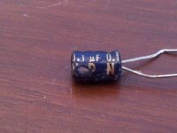
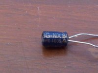
Black Gate NX HI-Q 0.1 uF, I put those in the power supply C62
C19, I use here 47uF Black gate N series.
C10 and C43 Sanyo OSCON 270uF, I will order by parts
C8 - Mcap EVO - Silver / Gold & Oil 0.1uF, I will also order by parts
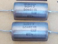
Let me know what brand I should order?Also remove C66 and insert a small 10nF PIO as well.
I also have PIO Russian caps, see picture.
Regards,
Rudy
Attachments
Last edited:
Glad you are back and ready to continue to work on Shiga. 🙂
BG over BG do not sound good, at least to my ears. Use PIO.
For C66 a 0.01uF russian PIO it is OK.
Regards,
Tibi
BG over BG do not sound good, at least to my ears. Use PIO.
For C66 a 0.01uF russian PIO it is OK.
Regards,
Tibi
C8 value?
Tibi,
There are two caps I would like to try in C8 position. I'm building a whole new system ( speakers, amp, DAC, Transport, and cables and power cords ) and will be burning it in for 300 hours in my shop, before bringing it into the house for serious listening. If I put both .1uf caps in parallel, in the C8 position, would .2uf hurt anything in this position. This way I can burn in both caps at once, and then remove one when I bring it into the house, listen for however long I want, and then change caps and listen some more. Will it work? Thanks.
- Home
- Source & Line
- Digital Source
- Shigaclone MKII Black - The builders Thread