As an advice for you : please do not use that linear regulator .Dear Tibi,
A. I do believe i am missing a few parts, i checked many times, but they are not there.
ADP151
1uF keramic 1206 smd (2 pieces)
Paul
Nothing by default (board as it is ) or instead use those 2 minireg that I am showing in this thread in case you want to do the High grade version.
Hi Tibi. After this few days.. The skip seems smoother on the same track and spot. Probably abit of run in? Hihi.. My friends will bring in BOW zz8 thos weekend and keep u guys update on the shoot out.
Shiga was working perfectly. I have it mounted on a sub chassis that will be mounted inside final box. I removed the Main Brd from the sub chassis and left the CD mechanics mounted on top, and did some fitting in the final box, drilled some mounting holes in the box, fitted the top panel. Bolted down sub chassis to box. I also disconnected the control brd from the display brd, and reconnected with some ribbon cable. Very fine gage. After fitting, I removed the sub chassis from the box, and reconnected it in my test setup. Now it doesn't work any more. When powered up she searches' around a bit before coming up with a zero, zero. After putting a disk on and hit CD Door, It spins the disk for a long time before it comes up with the same zero, zero. Way longer then it used to read TOC. The only difference in the test set up is that the display and control brds are now connected by a ribbon cable. Could that make any difference? Thank you all>
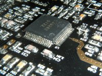
Board was fixed. As you can see a 22K resistor was broken.
Mounting smd parts vertically have certain advantages, but please take care when you handle the board.
Also please mail me your postage details on office@vico.....ro
Regards,
Tibi
Attachments
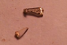
Board was fixed. As you can see a 22K resistor was broken.
Mounting smd parts vertically have certain advantages, but please take care when you handle the board.
Also please mail me your postage details on office@vico.....ro
Regards,
Tibi
Tibi,
My computer won't let me email to that address. Something about it being formatted wrong. But my computer is been acting weird lately. So I have sent you a PM on this forum. Thank you very, very much.
Tony G.
Shiga Black ?
I have a question. How did Shiga get the name Shiga Black? Where or when did it get, or what significance does the Black have. Or why is it Shiga Black?
I have a question. How did Shiga get the name Shiga Black? Where or when did it get, or what significance does the Black have. Or why is it Shiga Black?
Thank you for your response, Tony.
You are very welcome !
About name, just wanted to differentiate clearly from first Shiga. The pcb was made black and from here the name on PCB "Black SHIGA [MKII]"
Regards,
Tibi
You are very welcome !
About name, just wanted to differentiate clearly from first Shiga. The pcb was made black and from here the name on PCB "Black SHIGA [MKII]"
Regards,
Tibi
I appreciate support please
Dear Tibi,
I was able to switch on the whole system yesterday. A few strange things are happening and maybe you can help me with this.
When i switch on, what happens is:
A. The main 8V regulator drops the output voltage from 8V to about 6.5V.
B. The spindle goes inwards and does not stop.(!) The gear starts to rattle at the end and i removed power quickly.
C. I removed the lens cover, the lens goes down quickly and i hear a "tick".
D. Before the test i removed the laser solder blop. I "see" the laser diode with my multimeter.
I removed all cabling and i did some measurements.
1. The main regulator is the supplied 7808, i connected a 10 Ohm power resistor. Output Voltage is fine, 7.95 V under 0.8A load. Looks ok to me.
2. The secundairy regulators are 4 x LT1086-5, so fixed 5.0V. All 4 regulators show stable 5V within a few mV. Total current 103mA without the CD mechanism.
3. All IC's and regulators are cool.
4. The main regulator goes in shut down when i connect the 16 pin flat cable.
Before all testing i checked for short cuts on all chips, and this is ok.
What mistake could i have made? What did i overlook?
Thanks for the support last week, i understand about the AP151, the IR diode i could find, i got one anyhow, so issue at all.
Best regards,
Paul
Attachments
Dear Tibi,
I was able to switch on the whole system yesterday. A few strange things are happening and maybe you can help me with this.
When i switch on, what happens is:
A. The main 8V regulator drops the output voltage from 8V to about 6.5V.
B. The spindle goes inwards and does not stop.(!) The gear starts to rattle at the end and i removed power quickly.
C. I removed the lens cover, the lens goes down quickly and i hear a "tick".
D. Before the test i removed the laser solder blop. I "see" the laser diode with my multimeter.
I removed all cabling and i did some measurements.
1. The main regulator is the supplied 7808, i connected a 10 Ohm power resistor. Output Voltage is fine, 7.95 V under 0.8A load. Looks ok to me.
2. The secundairy regulators are 4 x LT1086-5, so fixed 5.0V. All 4 regulators show stable 5V within a few mV. Total current 103mA without the CD mechanism.
3. All IC's and regulators are cool.
4. The main regulator goes in shut down when i connect the 16 pin flat cable.
Before all testing i checked for short cuts on all chips, and this is ok.
What mistake could i have made? What did i overlook?
Thanks for the support last week, i understand about the AP151, the IR diode i could find, i got one anyhow, so issue at all.
Best regards,
Paul
Have you removed ferrite bead's L5 L9 etc.
When not in use, each regulator is bypassed by a ferrite bead.
Regards,
Tibi
Now i (finally) understand the regulator logic!
Thanks Tibi for your quick response.
Now i am finally getting the regulator logic and now i understand Danzup's answer from last week!!
I thought i must use some form of regulator in position V1 to V4. So i started with something that fitted, the LT1086-5. Later i would make the LT1763 boards.
That is wrong.
Now i understand that LA6541 on pin 11 and 12 together with Q2 provide a basic 5.0v for the whole board. The beads are short cuts (!) and dividing the 5.0 v to the different IC's. When you want to use an individual regulator, you have to remove the short cut, otherwise two regulators are in parallel providing 5.0V. That causes trouble. I thought that the beads where small inductors, that may cause interference with the LT1763. They are short cuts.
So what i will do is first remove the 4 regulators and see that the system comes alive. Then i will make some LT1763 boards / use the LT1086-5 where appropriate.
Some bells were ringing! Thanks for the support, Tibi.
Regards, Paul
Prinz,
You have connected the transport the wrong way to the main board. You need to reverse the 6 way cable connections. Explains why spindle going backwards and laser carriage is hitting the stops. I can see this mistake on the photo you supplied with your previous post.
Regards,
Aleks
You have connected the transport the wrong way to the main board. You need to reverse the 6 way cable connections. Explains why spindle going backwards and laser carriage is hitting the stops. I can see this mistake on the photo you supplied with your previous post.
Regards,
Aleks
Last edited:
Aleks,
Thank you for your comment. Hmm, i am not the first one to make this mistake.
I focussed on the pin numbers in this cable, i should have focussed to the what each wire does. 2 for spindle, 2 for sled, 2 for end switch.
At Friday i can work again on the system, i guess i am going to make it work next weekend. Thanks for the help,
Paul
Paul,
I've had just about all the problems one can have with this project. Fortunately none of them damaged anything. It just took a few days to iron them all out.
Single biggest issue was my failure to clean all the flux off of the main board. I also had a short in the 6-way cable but this wasn't visible as the plugs had heatshrink over them. Took me a day to work that one out. Another was small PCB that is adjacent to the laser lense was slightly crooked and the lense therefore wasn't parallel to the disc or the laser led, that cost me 2 hours.
It all worked out in the end and I'm very happy with the result. I'll try and help if you have any other issues, as it's fresh in my mind. Hi rez pictures always help.
Have fun
Aleks
Not enough solder....
Dear Aleks, Tibi and the others,
I solved the first issue, the large current flowing from the main regulator.
I removed the 4 pieces of 5V regulators to get back to a standard configuration. I still had a large current flowing when connecting the 16wire ribbon cable.
Then i started to measure some Voltages.
Vcc1 on pin 64 of the LA9242 was ok.
Vcc2 on pin 56 was ok also.
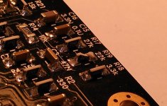
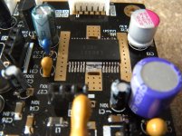
But... no Vr on pin 58. This should be 2.5V.
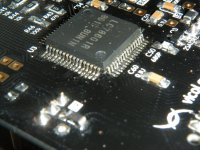
I turned the board upside down and made the picture, see attachment.
When looking on top, you can see it, only from the side, no solder...
After repairing it, i can put in the the 16wire ribbon cable, and things are stable.
Next step is to wire the 6wire cable for J2 and the transport visa versa.
Best regards, Paul
Dear Aleks, Tibi and the others,
I solved the first issue, the large current flowing from the main regulator.
I removed the 4 pieces of 5V regulators to get back to a standard configuration. I still had a large current flowing when connecting the 16wire ribbon cable.
Then i started to measure some Voltages.
Vcc1 on pin 64 of the LA9242 was ok.
Vcc2 on pin 56 was ok also.
But... no Vr on pin 58. This should be 2.5V.
I turned the board upside down and made the picture, see attachment.
When looking on top, you can see it, only from the side, no solder...
After repairing it, i can put in the the 16wire ribbon cable, and things are stable.
Next step is to wire the 6wire cable for J2 and the transport visa versa.
Best regards, Paul
Attachments
Hi Paul,
How's are things going now? I would be inclined to re solder all the pins on that I.C, some of them look marginal at best.
Have you got sweet music yet?
Aleks
How's are things going now? I would be inclined to re solder all the pins on that I.C, some of them look marginal at best.
Have you got sweet music yet?
Aleks
Last edited:
Status report from Paul
Hi Alex, Tibi and the others,
I am still strugling, sorry to say.
1. I made a new 6pin cable between the transport and J2.
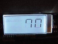
2. My back light on the display was not working and it took me ages to understand why. A. The ribbon cable supplied was 20 wires, and 18 had to be used. You have to remove 2 wires. I did not realise that because the 20 wire cable fits under the connector! See my provious pictures. But of course it doesn't work and it actually ruined my red connector. So i had to remove the red connector which was not so good for the PCB. I soldered the 18 wires directly on the PCB to avoid further issues. At least it works and the dispay shows 7n. (?)
3. I checked the frequency of the oscillator and it's working and fine.
4. I did a lot of cleaning to be sure that there are no issues there.
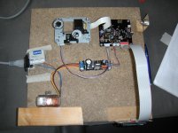
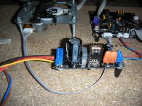
5. As you can see on the picture, i am using the build in regulator.
So status is:
A. The transport is silent. I can move the lens by hand, no force. Both motors for spindle and sled are not turning.
B. The ic's have a normal temperature, all 4x 5V + 2.5V ref are there.
What should i check more?
How can i start the system?
Should i check more voltages or frequencies?
Some help would be appreciated.
Best regards,
Paul
Hi Alex, Tibi and the others,
I am still strugling, sorry to say.
1. I made a new 6pin cable between the transport and J2.
2. My back light on the display was not working and it took me ages to understand why. A. The ribbon cable supplied was 20 wires, and 18 had to be used. You have to remove 2 wires. I did not realise that because the 20 wire cable fits under the connector! See my provious pictures. But of course it doesn't work and it actually ruined my red connector. So i had to remove the red connector which was not so good for the PCB. I soldered the 18 wires directly on the PCB to avoid further issues. At least it works and the dispay shows 7n. (?)
3. I checked the frequency of the oscillator and it's working and fine.
4. I did a lot of cleaning to be sure that there are no issues there.
5. As you can see on the picture, i am using the build in regulator.
So status is:
A. The transport is silent. I can move the lens by hand, no force. Both motors for spindle and sled are not turning.
B. The ic's have a normal temperature, all 4x 5V + 2.5V ref are there.
What should i check more?
How can i start the system?
Should i check more voltages or frequencies?
Some help would be appreciated.
Best regards,
Paul
Attachments
Hi Paul,
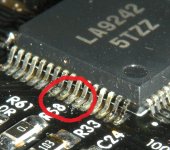
I suggest you to resolder all three IC's and add little more lead.
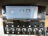
From your display, I see that you have some pins not soldered on LC78601 as well.
Regards,
Tibi
I suggest you to resolder all three IC's and add little more lead.
From your display, I see that you have some pins not soldered on LC78601 as well.
Regards,
Tibi
update Paul Sunday afternoon
Dear Tibi, Aleks and the others,
I have resoldered all 3 IC's. And i have tested 95% of the IC legs for conductivity. That is using a multimeter, one end on top of the ic leg, the other at the end of the pcb trace connected to it. I have seen no problems. I have added the result, please see the pictures.
I have tested conductivity between the LC78601 and the display. That is ok.
Results are:
A. Transport is silent.
B. Oscillator and Voltages and Uref are ok.
How can i isolate one part from another to test parts of the system. It is hard for me to understand where to continue searching.
What happens when the system starts up?
Thanks for the help already given.
Best regards,
Paul
Attachments
Paul,
As long your display do not properly shows digits, this indicate that LC78601 is not properly soldered, either ribbon cable was not properly crimped.
Measuring with multimeter will not indicate a bad solder joint because you had to push the pin toward PCB when you take measurement and this may make contact.
At power on the unit will search for CD toc, but for this a reset must be initiated and therefore J3 - cd door - cable must be in place and properly connected, otherwise the unit will stay "silent".
Regards,
Tibi
Last edited by a moderator:
Paul,
I know you said you made a new 6 way cable, but in the photo above it's still shown in reverse.
If you have corrected this, sorry for repeating myself.
Aleks
I know you said you made a new 6 way cable, but in the photo above it's still shown in reverse.
If you have corrected this, sorry for repeating myself.
Aleks
Feedback on Tibi and Aleks' comments
Dear Tibi, Aleks and the others,
I am only able to work on the project in the weekend, as i am travelling at the moment. So next week i can continue.
1. Tibi, maybe you are right about the multimeter, i'll check. I must say that i checked the ic by pushing down the pins with my fnger and looking on the display. Nothing changed on the display. I have used Danzup's method of using relatively a lot of solder, creating many short cuts. Then using the desoldering braid to remove the solder. The braid is removing maybe too much, i don't know.
2. About the CD door, i'll look in the ic datasheet how to cable this connector J3. Thanks for make me understand that it is required is cable it, leaving it as it is doesn't work.
3. Aleks: i have made a fool of my self, i repeated my mistake. I'll make the correct cable next weekend. I am consequently connecting pin 1 to pin 1 , that is my logic, which is wrong.
Thanks guys for all the help, best regards,
Paul
- Home
- Source & Line
- Digital Source
- Shigaclone MKII Black - The builders Thread