That seems about right, the IRFP250N has a little higher G-S (about 5V). It clips a little early on the negative side with R1=6K8, but it's no big deal when your are running with 40V rails  The 0,2V difference is G-S variations on the mosfets (does not matter either).
-Never stop listening to music Do you have a picture?
PS -try to use a 100nF decoupling cap close to the circuit to bring out the highs a little 😉
The 0,2V difference is G-S variations on the mosfets (does not matter either). -Never stop listening to music
Do you have a picture? PS -try to use a 100nF decoupling cap close to the circuit to bring out the highs a little 😉
Hi,
I am using MKP 1uF cap +220 uF elko close to the circuit, I don't think that adding 100 nf one would change anything. Maybe an IRFP240 or some other device would sound better. Highs are not bad, its just that a bit of sparkle is missing, when compared with ZEN V8. Otherwise unnoticeable.
If its of any help, I paired it with B&W DM 601 S3 speakers... (with closed port + additional sealed sub crossed at 65 Hz)
CD player is ROTEL RCD-02.
Vix
I would try a 100n multilayer ceramic or 100n poly cap in addition to the 1u/220u. But you are right, changing the mosfet is the biggest change in overall sound. Together with the output impedance of the source of course. What preamp are you using? What type of output El.cap are you using? If you really want to get brave and open up the sound, you can biwire and take the output to the tweeter before the output caps (provided there is no DC-path to ground in the loudspeaker tweeter filter). Just don't mix the two speaker wires 
I use Klipsch RB75, and they are sparkling nicely 😉
I use Klipsch RB75, and they are sparkling nicely 😉
Hi,
Thanks for an advice. I am using a BOZ as a preamp, with the volume control in front of BOZ. Output El cap is 10,000 uF, 50V nothing special (HITANO), bypased by 10 uF cap. Biwiring can be a good solution, since B&W DM 601 provides for that, but I don't know how does its crossover look like, so I am not brave enough to blindly try it. Will consider this option, though.
As for pictures, you can see them here (although the preamp is now in another enclosure):
http://www.passdiy.com/gallery/zen-v3-p2.htm
So it is the same as ZEN V3, only some components modified.
Maybe it does not belong anymore to a Pass galery? 😀
P.S. Nelson, if you read this, I owe you pics of ZEN V8😉
Thanks for an advice. I am using a BOZ as a preamp, with the volume control in front of BOZ. Output El cap is 10,000 uF, 50V nothing special (HITANO), bypased by 10 uF cap. Biwiring can be a good solution, since B&W DM 601 provides for that, but I don't know how does its crossover look like, so I am not brave enough to blindly try it. Will consider this option, though.
As for pictures, you can see them here (although the preamp is now in another enclosure):
http://www.passdiy.com/gallery/zen-v3-p2.htm
So it is the same as ZEN V3, only some components modified.
Maybe it does not belong anymore to a Pass galery?
😀 P.S. Nelson, if you read this, I owe you pics of ZEN V8😉
BOZ is a good preamp for SEWA 😉
As I recall (I have looked at a DM601s1 crossover) it does not have a resistor to ground before the cap, but you can easily measure it with a DMM across the + and - tweeter terminals -> no dc resistance=no dc path. The 10000uF Hitano cap is critical; I would use a good, low impedance cap here. Panasonic FC, Elna RJH, Sanyo MV-AX etc. Some might even get esoteric and use Black-Gate in this position. I have even used a Evox-Rifa PEH 200 22000uF here. Whatever cap you use, be shure to bypass it with a good, low value film cap. Even better, make a triplet (or quadruplet) with for instance (10uF), 1uF, 100nF and 10nF. Try a 10nF silvered mica for more treble sparkle 😉
I like to think of SEWA as my contribution to the ZEN series, as it follows the same design priciples, and I have learned a lot of the tecniques from Nelson. But it is no longer a Pass design, so we might have to remove your pictures from the passdiy server now 😉 😉 😉
-Are you using a fan on those tiny heatsinks?
Hi,
I may try biwiring; I will measure first. Will look to replace the output cap with a better one.
Of course we owe it all to Nelson. As he said, ZEN was not the best amplifier one could build, but it nevertheless gave us a good direction, and we learned a lot from that one.
It won't be right to say here something like "Sewa is better than Zen", but due to different topology, to me it sounds better than ZEN v3 did. But the whole point here is to learn something new, and perhaps train our ears by having a possibility to compare the sound of different topologies.
Big thanks
Vix
p.s Yes, unfortunately I am using fans!
Capacitance Multiplying PSU
Just Ordered a SEWA and starting reading up on Class A stuff 🙂
I came across this article http://sound.westhost.com/project15.htm about this class A power supply option, has anyone any experience with such a design? Are they feasible with SEWA and deliver as it promises?
(Actually, i made up my mind and order the parts from digikey already, the idea that i could leverage capacitance 10X is too appealing to me)
Chuck.
Attachments
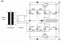
Is this supply really for poweramp
Anyway you will need only half of it
Mads shows a supply that looks similar, but if you look closely you will see that its a dual mono
Sewa is a single rail supply with +/ground
Anyway you will need only half of it
Mads shows a supply that looks similar, but if you look closely you will see that its a dual mono
Sewa is a single rail supply with +/ground
That will work.
Nelson gives his version in Zv3 http://passdiy.com/pdf/zen-ver3.pdf
Andrea Ciuffoli gives his version here:
http://www.audiodesignguide.com/PowerFollower/Follower_99d.gif
I would use atleast a 10000uF before the regulator though, and one rectifier/cap/regulator per channel.
My personal favourite is a pi-filter supply (like the proposed supply), but with inductors instead of resistors. But is very difficult to find suitable inductors. Besides, SEWA has very low outputnoise with the proposed supply (which is the same as the First Watt F1 supply) 😉
Edit: good point tinitus. You can only use the top half of the posted schematic. For a regulated supply I would do it like NP does in ZV3/4 and several of the following pieces. It would be practical to use the same mosfet as the main circuit (IRFP150N or the one you choose to use)
First the raw supply: http://passdiy.com/images/projects/zen-v4-f6_small.gif
Then the regulator part of ZV4 (only with 3x9V1 zeners)
http://passdiy.com/images/projects/zen-v4-f3.gif
Or, if one would like to do it overkill (only positive side is needed): http://passdiy.com/images/projects/zen-v5-f8_small.gif
This being said, a regulated supply is not needed, as the amp is dead silent with the current supply design 😉
Rev.B PCB
It seems to be a common misconception that the board is so small (25x53mm), the PSU/heatsinking demands are small aswell..
Well, wake up and smell hot transformers and heatsinks!
Mine is burning really hot. It is dissipating 46W each channel (23V, 2A) on 0,5'C/W sinks, and I am considering lowering the bias to 1,7A (39W dissipation) to relieve the mosfets of some off the hard work to come the next ten years or so.. At 2A bias, after 5-6hours my heatsinks and the entire chassis is unconfortably hot to the touch, while at 1,7A it stays in the "comfort -zone". The mosfets will survive in either situation.
Anyways, a good tip is to buy those ~3mm thick aluminium-oxide insulating washers (elfa # 75-654-27) for the mosfets and use them together with a little thermal grease. This way you will not have to bend the mosfets legs out from the board, and C3 will not make thermal contact with the heatsink, prolonging it's fate. Also, they give a better thermal connection to the heatsink.
Member
Joined 2002
Re: Rev.B PCB
I used these aluminium-oxide insulating washers on all my amps. I will never go back to a small thin pad..
Mad_K said:It seems to be a common misconception that the board is so small (25x53mm), the PSU/heatsinking demands are small aswell..
Well, wake up and smell hot transformers and heatsinks!
Mine is burning really hot. It is dissipating 46W each channel (23V, 2A) on 0,5'C/W sinks, and I am considering lowering the bias to 1,7A (39W dissipation) to relieve the mosfets of some off the hard work to come the next ten years or so.. At 2A bias, after 5-6hours my heatsinks and the entire chassis is unconfortably hot to the touch, while at 1,7A it stays in the "comfort -zone". The mosfets will survive in either situation.
Anyways, a good tip is to buy those ~3mm thick aluminium-oxide insulating washers (elfa # 75-654-27) for the mosfets and use them together with a little thermal grease. This way you will not have to bend the mosfets legs out from the board, and C3 will not make thermal contact with the heatsink, prolonging it's fate. Also, they give a better thermal connection to the heatsink.
I used these aluminium-oxide insulating washers on all my amps. I will never go back to a small thin pad..
Re: Capacitance Multiplying PSU
Large caps, large transformers and a large chassis/heatsinks is what makes a Class A amp for me 😉
Remember, you will also have to cool the regulator transistors.
25V caps are cheap compared to the increased price you will have to pay for bigger heatsinks when using a regulator. Maybe not so severe with the cap. multiplier you posted, but definately with a mosfet based regulator supply (minimum 8W dissipation per regulator)
Anyways, fans are very helpful in getting trafo/chassis and heatsink temp down from a undersized amp. I just don't like them because of the noise and compromised reliability.
angchuck said:
the idea that i could leverage capacitance 10X is too appealing to me
Chuck.
Large caps, large transformers and a large chassis/heatsinks is what makes a Class A amp for me 😉
Remember, you will also have to cool the regulator transistors.
25V caps are cheap compared to the increased price you will have to pay for bigger heatsinks when using a regulator. Maybe not so severe with the cap. multiplier you posted, but definately with a mosfet based regulator supply (minimum 8W dissipation per regulator)
Anyways, fans are very helpful in getting trafo/chassis and heatsink temp down from a undersized amp. I just don't like them because of the noise and compromised reliability.
HI
I have a extra set of gold plated pc boards (SEWA RevB type) what I orderd from MKH. If someone from Canada or from USA intrested you can save on the shipping .
I also offer a set (4pc) IRPN150N mosfets &(2pc) BC850C transistors with the pc boards .
I only offer the transistors and mosfets if you take the pc boards .
If you are intrested please contact by e-mail.
Thanks
Regards
BOSEWA question
Hi Mads!
How are you doing?
What about the BOSEWA?!? Is there any news?
Next week We will do a little listening test between ZV9 and SEWA. This time it will be realy a little test: only the two amps and 4 pre and 2 loudspeaker. 😀
One more BOSOZ grounding-shorting question:
between -in and ground I use only the R14 100K resistor to short the input. Is it bad? Need I short it direct with a jumper? The sound is excellent.
Greets:
Tyimo
Maybee this has been up before,what is the input sens of SEWA?
It would be possible to make it a hybrid with a tube at the input?🙂
It would be possible to make it a hybrid with a tube at the input?🙂
I mean with a tube like ECC86,like an experiment,havent assembled it yet I am finnishing the box.
Ryssen said:Maybee this has been up before,what is the input sens of SEWA?
It would be possible to make it a hybrid with a tube at the input?🙂
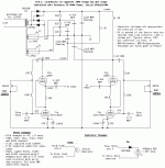
Already working on that... something conceptually like the attached but with a single tube per amp (6H23p/ECC88 probably) since my available trafos dictate mono-blocs
The circuit shown is the modified output stage -- the tubification of -- my Technics ST-8080 tuner.
dave
Attachments
How are planning to do connect the tube, anode at C2 or direct coupling?I was thinking of ECC86 that can run on about 25v.🙂


Probably cap-coupled... this front-end has more utility than just the SEWA, and we have lots of the ECC88 family tubes lying around (and no ecc86).
dave
dave
- Home
- Amplifiers
- Pass Labs
- SEWA - Seven Watt Amplifier