truer words were never spoken...if you want to obey your own decision ........ just don't open the file
if you open it, you'll change something .... been there..... and still I am

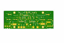
As promised, here are a few more details regarding the PCB and build I shared a few posts ago...
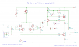
First off, don't be fooled into thinking there's anything original here. What you see is an Aleph J, as designed by Nelson Pass. My only edits to the circuit were:
- parallel the front-end J74 jfets (à la J2 to reduce noise and increase transcoductance, or at least that's what I've read 🙂)
- bjt and accompanying parts for front-end CCS replaced with a K170 jfet (à la J2)
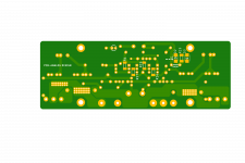
Outside of those circuit edits, my goal was to make a PCB that fit my own unique desires and parts on hand. I also wanted to make tweaking the circuit easy. I started the layout in Kicad, but quickly decided that I have much to learn and asked Prasi to work up a layout.
Here are a few interesting features and requirements of the PCB:
- board is small and fits UMS
- two output transistors (one IRFP-240 for CCS, and one Semisouth for output)
- optional ground lift as SMD on bottom side of board
- 100R gate resistors on jfets are SMD on bottom side of board
- The 1.2K resistor that traditionally determines the amount of AC gain/loopback the Aleph Current Source sees is replaced by a 2K pot.
- All pots have provisions for being replaced by THT resistors once final values have been established
- Film bypass resistors have been increased to 1uf, or whatever you can fit (27.5mm pitch max)
- The four paralleled .47 3W current resistors at the output were replaced by a single .1 to-247 resistor. If you have a 300mm chassis that has the UMS pattern, you'll notice a center hole that's slightly above the bottom row. This resistor uses that hole for mounting, though you could easily fashion a .1 5W resistor to work as thru-hole.
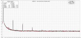
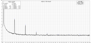
After nearly a week of listening and measuring, I can say that the boards work just as expected. Offset and bias are stable, and measured performance is great. Its hard for me to subjectively compare this version to the previous AJSS version I implemented with the store boards. I will say that its never sounded better, and I'm definitely happy I went through the process of producing these boards.
As mentioned above, I made these boards with my own, unique interests in mind. I'm confident that RainfallSky's (and others) boards will appeal to more people and perform beautifully. That said, if you have an itch to use a bunch of expensive jfets and want to give this board a go, I've attached the Gerbers. I also might have a few sets available at cost, but will need to double-check.
Finally, I can't say enough nice things about Prasi. He's a true professional and a master at his craft!
Building notes:
- SMD resistor are 0207 melf
- ground lift diodes are SMB 1N4007
- here's the to-247 resistor I used, though anything will do.
- 220uf are 5mm or 7.5mm pitch
- 1uf bypass caps provide are 27.5mm max
- I used this for C6
First off, don't be fooled into thinking there's anything original here. What you see is an Aleph J, as designed by Nelson Pass. My only edits to the circuit were:
- parallel the front-end J74 jfets (à la J2 to reduce noise and increase transcoductance, or at least that's what I've read 🙂)
- bjt and accompanying parts for front-end CCS replaced with a K170 jfet (à la J2)
Outside of those circuit edits, my goal was to make a PCB that fit my own unique desires and parts on hand. I also wanted to make tweaking the circuit easy. I started the layout in Kicad, but quickly decided that I have much to learn and asked Prasi to work up a layout.
Here are a few interesting features and requirements of the PCB:
- board is small and fits UMS
- two output transistors (one IRFP-240 for CCS, and one Semisouth for output)
- optional ground lift as SMD on bottom side of board
- 100R gate resistors on jfets are SMD on bottom side of board
- The 1.2K resistor that traditionally determines the amount of AC gain/loopback the Aleph Current Source sees is replaced by a 2K pot.
- All pots have provisions for being replaced by THT resistors once final values have been established
- Film bypass resistors have been increased to 1uf, or whatever you can fit (27.5mm pitch max)
- The four paralleled .47 3W current resistors at the output were replaced by a single .1 to-247 resistor. If you have a 300mm chassis that has the UMS pattern, you'll notice a center hole that's slightly above the bottom row. This resistor uses that hole for mounting, though you could easily fashion a .1 5W resistor to work as thru-hole.
After nearly a week of listening and measuring, I can say that the boards work just as expected. Offset and bias are stable, and measured performance is great. Its hard for me to subjectively compare this version to the previous AJSS version I implemented with the store boards. I will say that its never sounded better, and I'm definitely happy I went through the process of producing these boards.
As mentioned above, I made these boards with my own, unique interests in mind. I'm confident that RainfallSky's (and others) boards will appeal to more people and perform beautifully. That said, if you have an itch to use a bunch of expensive jfets and want to give this board a go, I've attached the Gerbers. I also might have a few sets available at cost, but will need to double-check.
Finally, I can't say enough nice things about Prasi. He's a true professional and a master at his craft!
Building notes:
- SMD resistor are 0207 melf
- ground lift diodes are SMB 1N4007
- here's the to-247 resistor I used, though anything will do.
- 220uf are 5mm or 7.5mm pitch
- 1uf bypass caps provide are 27.5mm max
- I used this for C6
Attachments
-
 AJSS-clone-codyt.png221.7 KB · Views: 565
 -
 ajss-low-distortion.png134.7 KB · Views: 267
 -
 ajss-50perc.png110.1 KB · Views: 469
 -
ALEF-R0.2 - tweaks_2021-03-28.zip244.1 KB · Views: 146
-
 ALEF-R0.2 - tweaks-btm.png73.8 KB · Views: 484
 -
 ALEF-R0.2 - tweaks-top.png92.6 KB · Views: 493
 -
 ALEF-R0.2 - tweaks-lay.png84.5 KB · Views: 540


codyt,
I feel like a kid in the candy store with so many great choices. Great work and wish that there was 48 hours in the day, so I could devote more time to learn more and build these amps.
I feel like a kid in the candy store with so many great choices. Great work and wish that there was 48 hours in the day, so I could devote more time to learn more and build these amps.
Nothing to learn on this one. All I did was take the AJ, make it more complicated, and add some more hard to get jfets. 😀

Thanks!
I forgot to mention that the front end requires careful matching to ensure best performance. My J74’s were matched at around 8.5mA Idss and the K170 at around 7.7mA Idss. One can use different values, but I’d recommend a similar ratio.
I forgot to mention that the front end requires careful matching to ensure best performance. My J74’s were matched at around 8.5mA Idss and the K170 at around 7.7mA Idss. One can use different values, but I’d recommend a similar ratio.
codyt,
I feel like a kid in the candy store with so many great choices. Great work and wish that there was 48 hours in the day, so I could devote more time to learn more and build these amps.
Also on horizon are Tokin and other Papa SIT projects, ZM's SissySIT R.3, ZM's Old Soul (not literaly), New Version of F5 and so on.
I never seen GreedyBoyz so confused what to build. 😀
Found a little error.
No mask zone around Zeus pad symbol is not covering copper in a few places.
Happened because of not ideal built in image convertion.
Fixed that by hand.
In a previous versions those places would be covered by mask so nothing scary.
Gerbers file V1.12 with a fix is in attach.
No mask zone around Zeus pad symbol is not covering copper in a few places.
Happened because of not ideal built in image convertion.
Fixed that by hand.
In a previous versions those places would be covered by mask so nothing scary.
Gerbers file V1.12 with a fix is in attach.
Attachments
Nothing to learn on this one. All I did was take the AJ, make it more complicated, and add some more hard to get jfets. 😀
Shouldn't you be giving Zen Mod credit for this quote? 😉
Thanks!
I forgot to mention that the front end requires careful matching to ensure best performance. My J74’s were matched at around 8.5mA Idss and the K170 at around 7.7mA Idss. One can use different values, but I’d recommend a similar ratio.
Cody, how do you calculate Idss for 2SK170 or where could I read about it?
I tought what if.. what if I too try 2SK170 NJFET for CCS but leave SJ74 as a pair.. 🙂
I am not good at at ltspice so I took Patrick J2 files and start doing random things redrewing it to Aleph J.
Not sure everything is error free but 2SK170 dissipate 216mW. 😱
If I add 1K resistor before 2SK170, resistor dissipate 77mW and 2SK170 dissipate 159mW.
And 2 output stage transistors are dissipating 74W each.
74 Watts each for the output stage devices is on the upper end of what they can tolerate. It is possible, but will require careful mounting of the transistors to the heatsinks to ensure efficient thermal transfer. I use ceramic (aluminum oxide) insulators with a little bit of thermal grease. The heatsinks need to be dressed with a diamond or Arkansas whetstone to make sure the surface is smooth and flat. The thermal grease will prevent air from being present.
Cody, how do you calculate Idss for 2SK170 or where could I read about it?
I tought what if.. what if I too try 2SK170 NJFET for CCS but leave SJ74 as a pair.. 🙂
I am not good at at ltspice so I took Patrick J2 files and start doing random things redrewing it to Aleph J.
Not sure everything is error free but 2SK170 dissipate 216mW. 😱
If I add 1K resistor before 2SK170, resistor dissipate 77mW and 2SK170 dissipate 159mW.
And 2 output stage transistors are dissipating 74W each.
I just measured the Idss, since I didn’t use any kind of dropping resistor. Concerning the dissipation, you calculations may very well be accurate, though I can say that they barely get warm on my boards. Regarding output devices, 1.7A x 50v (25v swings) = 85w dissipated across two devices (/2) = 42.5W per device. Or at least that’s the math I’ve been using 😀 A trusted source has suggested 50W as a max for the SS parts, so I’m not too worried. Proof is really at the heat sinks, and mine measure around 53C
Last thing I’ll leave you with - I was told by more than one person (and have read it many places) that 2SK170 for a CCS is a waste. I tend to believe them, but I just had plenty of 170s and figured “what the hell”. 🙂 Point being that I doubt you’d see justifiable performance increase in using them. Can’t say that I have.
Last edited:
I just measured the Idss, since I didn’t use any kind of dropping resistor. Concerning the dissipation, you calculations may very well be accurate, though I can say that they barely get warm on my boards. Regarding output devices, 1.7A x 50v (25v swings) = 85w dissipated across two devices (/2) = 42.5W per device. Or at least that’s the math I’ve been using 😀 A trusted source has suggested 50W as a max for the SS parts, so I’m not too worried. Proof is really at the heat sinks, and mine measure around 53C
Last thing I’ll leave you with - I was told by more than one person (and have read it many places) that 2SK170 for a CCS is a waste. I tend to believe them, but I just had plenty of 170s and figured “what the hell”. 🙂 Point being that I doubt you’d see justifiable performance increase in using them. Can’t say that I have.
About output stage transitors dissipation I might have errors in my ltspice simulation.
I have some 2SK170.
I though with resistor + 2SK170 I can simplify layout and double output trace.
But I can't figure what Idss I need for CSS JFET.
I feel I ask stupid questions but I kind of lost a bit.
74W per mosfet isn't figure you want for your domestic amp, playing cruisin' music all day
that's more Hot Rod/dragster territory - blast fast, blast short, blast
that's more Hot Rod/dragster territory - blast fast, blast short, blast
^ This is true. Even at 45W per device, my recommendations for ensuring good thermal transfer still hold.
About output stage transitors dissipation I might have errors in my ltspice simulation.
I have some 2SK170.
I though with resistor + 2SK170 I can simplify layout and double output trace.
But I can't figure what Idss I need for CSS JFET.
I feel I ask stupid questions but I kind of lost a bit.
I believe it’s around 90% of the Idss of your J74’s. ZM is better person to ask though
I believe it’s around 90% of the Idss of your J74’s. ZM is better person to ask though
Thank you!
74W per mosfet isn't figure you want for your domestic amp, playing cruisin' music all day
that's more Hot Rod/dragster territory - blast fast, blast short, blast
I might have not obvious errors in my sim.
Or I need to rest and do something else for today.. )
Spice model is in attach.
Patrick wrote SemiSouth.lib should be in the same folder for sim to work.
It was his J2 before I start to edit file.
Attachments
- Home
- Amplifiers
- Pass Labs
- Semisouth Aleph J?