I also recommend edits to R24 be saved as a last resort, and only monkeyed with if one has some way of measuring distortion. This resistor determines the gain of the modulated current source as was chosen to work with the stock values. That said, if you decide to mess around with it’s value, Zen Variations 2 is required reading.
ZM, does this comment imply that R9 should stay as 221 ohm and R16 stay at .47 ohm?Pa did remove it in J2
as I explained in PM - do not alter values in Aleph CCS, while you can play with source resistor of SS , somewhat altering OLG thus THD Spectra, in some way and measure
R9 - really don't care is it 220R or 470R, I am not sure that I can hear difference in Aleph CCS
regarding source resistor and ratio of output sense resistor group, I've explained that to you - parallel sum of source resistors in Aleph CCS - parallel sum of sense resistors is 50% of first
so you got it right here - have one source resistor of 0R22, sense group is 0R1175
of course that you can alter any of these, but then you must play with value of R24, to establish preferred Aleph CCS AC gain ....... and from years of reinventing the wheel experience, I learned that Pa's settings are right where they're keeping most people happy
it's practical at least to start from that, so you can go back to same spot , after few months of loosing your time in experimenting
Last edited:
Sorry ZM, I wasn't trying to be dense or off-putting. I missed that guidance somewhere. My intention is to build Aleph J with Semisouths changing only what's necessary.
Sorry ZM, I wasn't trying to be dense or off-putting. .....
well, I didn't had any impression that you're trying that

when you see me not replying - either I didn't read something ( so not knowing that there is reply I need to make) , or - really ultrarare occasions - I felt off- put , so I'm just outa here .........
(lately put few creatures on my ignore list, it simply doesn't compute corresponding at all
I know how big fool I am , some evidently are way ignorant about own stupidity)
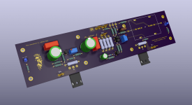
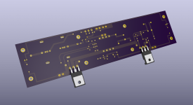
I had my Aleph J boards out of the chassis yesterday and took this picture for anyone that wants a visual reference. I’m using .22R source resistors, which should maintain the overall balance of the Aleph current source at a bias around 1A7. I removed the overcurrent protection on these boards, but it’s not necessary.
Attachments

I’m taking this as confirmation that I didn’t say something completely wrong 😀
Also, I hope you noticed the MKC Philips cap - you’ve converted me to polycarbonate 😎
I had my Aleph J boards out of the chassis yesterday and took this picture for anyone that wants a visual reference. I’m using .22R source resistors, which should maintain the overall balance of the Aleph current source at a bias around 1A7. I removed the overcurrent protection on these boards, but it’s not necessary.
Hi Cody,
Just so I’m clear (I’m a little fuzzy lately), .22R resistors for both the CCS transistor and the Semi South?
Thanks!
Hi Cody,
Just so I’m clear (I’m a little fuzzy lately), .22R resistors for both the CCS transistor and the Semi South?
Thanks!
Yes, that's what I have here. You could play around with different values for the output (Semisouth), but the important value is .22R for the top, current source device. Not that it can't be adjusted, but if you go down that path, you'll be adjusting other parts of the circuit. I measured this configuration and got around .04% THD. If you wanted to lower that number, you could raise the value of the output source resistor. Maybe .33R or .47R.
Also, I hope you noticed the MKC Philips cap - you’ve converted me to polycarbonate 😎
I never tried pc... better to go with NOS wima mkc4, ero1860 or philips 344? Thanks
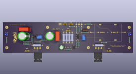
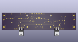
Layout so far. DIYAudio UMS heatsink compatible, 3U or bigger.
Same layout as befor but with a few changes and added Hum Breaking Resistor sugested in another thread.
Overcurrent protection removed. (It was also removed in previous layout too)
Zen Mod suggested double power traces on both sides.
Some are doubled now.
Same layout as befor but with a few changes and added Hum Breaking Resistor sugested in another thread.
Overcurrent protection removed. (It was also removed in previous layout too)
Zen Mod suggested double power traces on both sides.
Some are doubled now.
Attachments
I never tried pc... better to go with NOS wima mkc4, ero1860 or philips 344? Thanks
I’ve only tried Philips. I have some of the Wima mkc4, but haven’t tried yet. This is a question for ZM 🙂
Looks good! Is that ‘Nelson, the God of Class A’ depicted on there? 😀
Naaa... too short hair
Thanks for the info, Codyt!
Looks good! Is that ‘Nelson, the God of Class A’ depicted on there? 😀
It's Zeus. And he is there for no particular reason. 🙂
You could also call him Jupiter or grumpy hairy bearded old man. 😀
- Home
- Amplifiers
- Pass Labs
- Semisouth Aleph J?