As many others have stated NTC's, when correctly calculated are a quick easy and cheap solution. Having designed and built , delayed zero crossing detector based Triac, and simple R C tc transistor controlled relay taking an 50 W 5 - 20 R input I limiting R out of Active line, NTC are as above. BTW the heatshrink around the NTC's is to stop the little ceramic and metal particles from exiting their alotted installed space faster than the speed of sound when failing, which is quiet common in (>500 VA) DC-DC converters SMPSU's, Welders etc.
Hi Mike (OP),
Lot's of varying opinions here. Because I come from a service repair background I've really formed my opinions from what I have seen in successful designs. Good solutions use either the resistor and relay solution, and I have seen thermistors used too. For an amplifier design, I would go with the resistor-relay solution. If you can use the rectified secondary supplies, just put the relay coil across the DC supply. If that exceeds the coil voltage, use a dropping resistor. Once teh supply reaches the pull in voltage of the relay, the contacts will close and short out the series resistance. I've seen values of 2R2 to 22R for the series resistor depending on the size of the amplifier. Both methods are called "soft start" circuits. You don't need a timer to drive the relay as once the supply is close to the pull-in voltage, it's about the right time for the resistor to be shorted out.
For most amplifiers, 10R is about right. No chart or equations. Just what I have seen the most of over 40 years .
-Chris

I am also in a similar dilemma. The point that worries me is that, usually, these NTC devices are shorted out by some sort of relay after a few secs max. If the relay fails to operate, the amp may still continue running, but now with the thermistor running at around 150 degrees or C. This is dangerous.
I am looking for exactly the reverse, a PTC, which when heats up (ie relay not engaging) increases its resistance and hence stabilising the whole system at a much lower current flow.
The device I am looking for would be around 33 to 50 ohms to start with, and a max current of about 3-4 amps or so for a few seconds (until relay engages). If the relay does NOT engage, the temp goes up and resistance also goes up hence effectively shutting down the mains to the transformer primary.
Unfortunately, I have not found a PTC with those characteristics. Does anyone know of one ?
Thanks
NTC's are typically specified to operate at least to 175C and can be above 200C. So I wouldn't consider derated operation at 150C as dangerous. NTC's are like valves - they get hot and need to be located appropriately, and with signs/labels if it is not obvious that it is hot (although its use on the mains AC side of the circuit makes it a hazard for other reasons).with the thermistor running at around 150 ese NTC dedegrees or C. This is dangerous.
Hi cakyol,
All I can do is agree with trobbins on this. I use them, mounted on a terminal strip - just like they did in the 60's.
-Chris
All I can do is agree with trobbins on this. I use them, mounted on a terminal strip - just like they did in the 60's.
-Chris
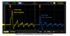
Rod Elliott's web page contains an actual oscilloscope photo of inrush current. When driving an inductive load such as the primary of a power transformer, "ELI the ICE man" prevails, just as they taught you in your university EE curriculum: the peak of the sinusoidal current corresponds to zero sinusoidal voltage. "Switch at the voltage zero crossing" is therefore the worst case scenario, and that's why Rod Elliott runs his tests & captures his scope traces with on/off at voltage zero crossings [yellow trace]. The much less difficult scenario, switching at the voltage peak, results in considerably lower inrush current [blue trace].
If you read the entire page (link), you'll find that Rod recommends bypassing the inrush current limiter a few seconds after turn on, figure 2 below. Other authors do not use or recommend bypass, perhaps most notably Nelson Pass's Class A First Watt amplifiers, many of which are sold as bare PCBs in the diyAudio store.
_
Attachments

Hi Mark,
I only bypass fixed resistors with a relay. I don't bypass the surge resistors, but it might be nicer to do so.
-Chris
I only bypass fixed resistors with a relay. I don't bypass the surge resistors, but it might be nicer to do so.
-Chris
Thanks for all your responses. I am still somewhat reluctant to have any component in a solid state enclosure to be allowed to run at 150+ degrees C. Maybe only temporarily but not for a long time. It just is not a good idea. But again, thanks for all your suggestions.
And again, my emphasis is on the fix for when the relay does NOT engage due to a relay fault. This is the condition I am trying to protect against.
Thanks
Thanks
Thanks for all your responses. I am still somewhat reluctant to have any component in a solid state enclosure to be allowed to run at 150+ degrees C. Maybe only temporarily but not for a long time. It just is not a good idea. But again, thanks for all your suggestions.
Hey Cakyol not sure if this is what you are looking for- they do make bimetal switches (thermal switches) that trigger at certain temperatures. So they are normally open or normally closed and will flip when the heat reaches a certain temp, and flip back when reduced below that temp (with hysteresis).
You could have them open circuit your power transformer (thus turning off the amplifier) when the output device heat sink reached 60C or something like that. Once it cools off it will automatically flip and turn it back on.
Here is a link- Disc Bimetallic Thermostats - Cantherm | DigiKey
I have them on a couple of my amps- use them to flip on some warning LEDs when the heat sink temps get to a certain range.
Hi Igreen, I already have such temp sensors on the heatsinks but cannot use them for the purpose I require. First, they would not be fast enuf to react in time, second, I want to detect the condition BEFORE the heating occurs and avoid it from happening in the first place.
Thanks tho
Thanks tho
.If you read the entire page (link), you'll find that Rod recommends bypassing the inrush current limiter a few seconds after turn on, figure 2 below.
Bottom of this page also makes reference to doing that. In this case to allow the thermistor to cool down for re-cycle in event of a power out - on event.
Thermistors used to be considered as noisey resistors. Has that notion been discarded?
Hi Mark,I only bypass fixed resistors with a relay. I don't bypass the surge resistors, but it might be nicer to do so.-Chris
Following this fellow's page takes a little work as some of the noted connections are located on other pages and his added buck/boost switching stuff is part of the mix but the basic idea is so simple it's hard not to like it enough to consider use on most anything high powered. His design explanatory thumbnails are also a nice touch.
You know what? You want the surge resistor to burn open if the relay or triac doesn't engage. The condition this is true for is shorted rectifier or outputs. This condition drops the supply rails and allows a replay to drop out. At this point you do want the surge resistor to open.
It sounds counter-intuitive. I thought so at first, but after servicing many amplifiers with burned out surge resistors, I noticed that the open resistor saved most amplifiers from more serious damage.
BTW, in that linked diagram with the bimetallic strip against the resistor has a really rotten trait. It cycles. You really do not want the strip contacts opening and closing. It was one of the first features I got rid of in my Eico HF-87 tube amplifier.
-Chris
That sounds like good advice and I'm glad you bring it up though of course it begs the question. Shouldn't the fuse take care of that?
I didn't see the bimetal strip though it's not the sort of thing I'd think of using here. Strange thing to put in a circuit like this. It would just boot the amp back up again once it cooled, no?
I didn't see the bimetal strip though it's not the sort of thing I'd think of using here. Strange thing to put in a circuit like this. It would just boot the amp back up again once it cooled, no?
Yup, exactly why they cycle.
If you want the limit the fault energy, dropping the surge resistor in circuit is the best way to do that. It only costs a resistor. I have seen them come in with the fuse okay, and with it blown. Only a fault will collapse the supplies, or a bad AC feed. That will also work to make the hurting stop. 🙂
The name of the game is to limit the energy in a fault situation any way you can. Carver amps shut down very nicely. But your standard power supply can't do that, so a surge resistor will cover dual duty. These resistors usually range from 2R2 to 10R. 5W is the typical wattage rating.
-Chris
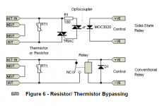
If the relay fails to engage, there is no predicting how the current limiter resistor will fail. It may catch fire or fail with an open circuit. I am choosing "flame proof" resistors for my design just in case and will most likely use the SSR version of the relay to monimize the possibility. I do not want to give the insurance company any excuses if and when a fire may start 🙂
- Status
- Not open for further replies.
- Home
- Design & Build
- Parts
- Selecting NTC Inrush Current Limiters