I want to add an NTC inrush current limiter to a fairly large amplifier and would like some advice about selecting one that will work. I am making modifications that allow me to turn on my entire system at once and I want to limit the inrush current of the two big amps that are part of the system. I’ve read through several DIYA threads but none answer my questions.
Using one of the amps as an example, operating voltage is 120vac (US-based) and it has two banks of 2x15,000uf filter caps for a total of 60,000uf. I don’t have any/many specs on the transformer, although I am aware that the transformer can affect the choice of the NTC. Each of the diode bridges is rated at 25 amps. Measurements show a steady state current draw of about 0.8 to 0.9 amps (while playing at typical volumes).
Based on some commonly published calculation approaches, I’ve come up with the following:
For the filter caps, the stored energy would be: CVpk[2]/2 = 867 Joules absorbed by the NTC. Based on the commonly accepted practice of limiting the inrush current to no more than half of the rectifier bridge rating, we have about 12 amps maximum inrush current (or is it 25 amps, 12 for each bridge?). From that, the minimum resistance, Rmin, would be 14.2 ohms @25C. This yields device parameters as:
Rmin = 14.2 ohms
Energy = 867 Joules
I ss = 0.85 amps
Peak volts = 170
All of this leads me to (for example) an Epcos/TDK NTC device from Digikey (495-2077-ND) that has the following specs: 15 ohm cold resistance, 20% tolerance, and 1.8A steady state current.
Are the above calculations reasonable and would a device like this suit my needs?
Rectifier diodes have a peak current rating many times higher than their continuous current rating, so no need to worry about that. The main reason for inrush current limiting is to prevent the lights dimming when you switch on the amp. It will also reduce the DC transient in the mains transformer and so reduce the initial mechanical hum.
You might consider purchasing an inexpensive "Kill-A-Watt" device, something like (example), and using it to measure your amplifier's power consumption when playing music loudly. This gives you an estimate of the current your amplifier draws from the AC mains.
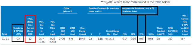
Then you could choose an NTC ICL whose resistance when fully heated up (I'll call that "R_hot") drops something like 1% or 2% of the AC mains voltageNow that you know what value of R_hot to shoot for, select an NTC ICL with sufficient current rating {red rectangle in attachment} and with the largest available (R_cold / R_hot) ratio {black rectangles}. The bigger the (R_cold / R_hot) ratio, the more limited your inrush current will be.
It's just a thought . . . . .
Then you could choose an NTC ICL whose resistance when fully heated up (I'll call that "R_hot") drops something like 1% or 2% of the AC mains voltage
- (0.01 * Mains_Voltage) = Average_Current * R_hot
It's just a thought . . . . .
Attachments
The 60,000 μF cap bank is charged to 170 V directly off the mains? That's unusual! DF96 is right tho as usual: a 25 amp full-wave bridge rectifier has peak ratings at LEAST up to 5× that for instantaneous inrush current.
More usual is that there is a transformer that serves to lower the voltage to a more sane level and to isolate mains/wall power from the audio-signals side of the box. Having a direct connection to mains is so dangerous in practice that making amplifier suggestions on this forum is banned with maximum prejudice. So… I'm guessing your big amps have nice BIG transformers.
Once you go down that logic, you then have to question your Vpeak proposition (of 170 V). If measured, I'm betting you'll find a voltage closer to the range of 40 to 100 volts, depending on the power rating of the amplifiers. Indeed, one of the reasons there is a multiple of 2 number of capacitors is that very frequently amplifiers are set up with a 3 rail power supply. +volts, zero/ground, -volts. This simplifies the balancing of the output without requiring large non-polarized DC blocking capacitors in front of the speakers.
So… my point is that your energy storage calculations in turn need to be adjusted, accordingly.
Also, note this about inrush limiters: they have decidedly non-linear current passing behavior. They also "turn off" at about 130°C, if they've absorbed enough energy quickly to raise their temperature that high. Once triggered, they need to cool off to again revert to lower resistance. This kind of thing can damage your amplifiers…
To conclude - when I consider what you are trying to achieve, I am left with wondering whether a 2 to 3 second time-delay relay might not be the better answer. Either to just delay the power-up of the Big Amplifiers entirely (and not worry about inrush), which protects your house breaker circuits, or in a more sophisticated way, having a 2 Ω power resistor in parallel to the relay that serves as a simple inrush limiter. In 2 or 3 seconds, the relay shorts out the resistor, reducing it to zero Ω, taking it out of the circuit. By that time, your power amplifiers are happily powered up and ready to go.
Just saying.
From a different angle.
GoatGuy
I have a feeling it's more likely you will want the DigiKey part number 495-76103-6-ND.
Its max steady state current is 1.3 amperes which, I'm guessing, is just a wee bit more than your amp draws when playing LOUD music into inefficient (low sensitivity) speakers: the worst case.
Its resistance when hot is about 1 ohm (datasheet page 4), so the voltage across the NTC ICL in steady state is (1ohm * 1.3amp) = 1.3 volts, which is about 1% of your 120VAC mains. You're not squandering huge amounts of additional power just to keep the ICL hot.
Its resistance when cold (25C) is 33 ohms, so you get a very nice 33-to-1 ratio of cold resistance to hot resistance. Even if the entire remainder of the primary circuit acts as a completely perfect dead-short at power on, the cold ICL means primary inrush current is less than 4 amps. Nice.
edit- if you decide you want even greater surge energy capability than one NTC ICL can provide, you can connect two of them in series. Calculate the required Rcold etc for each one, and put them in series. If one of them gets hotter than the other, its resistance goes down so its temperature goes down. Thus you get thermal stability rather than thermal runaway.
Last edited:
It's a good idea to bypass a thermistor (or resistor) after it has done it's job with a relay. Information here should help you size it appropriately Soft-Start Circuit For Power Amps
OK, let's step back and think about what happens when you turn on your amp with a linear PS (transformer-->bridge rectifier-->cap bank).
With the power off:
the transformer has no magnetic field
the caps are discharged
When you apply mains power:
it sees some copper wire between hot and neutral. That's the transformer primary. This might be only a couple of Ohms resistance. AC power in the USA is 115/120Vac RMS which comes to about 170Vac peak voltage. Let's say for simplicity sake your large transformer has a primary resistance of only 1 Ohm when off. Apply 170V peak and guess what, you've got 170 Amps of current immediately trying to flow. That will instantaneously blow the line fuse and or trip the circuit breaker in your house. Even if your transformer is "smaller" like 300VA it still probably has only around 3-4 Ohms resistance when not energized and the inrush just through the primary at turn on can be enough to blow a fuse unless you oversize it or make it slow-blow, both of which reduce its protection under normal conditions.
So, one of the main purposes for inrush limiting is to prevent the inrush to the transformer regardless of what comes after it.
Next up we have the diode bridge. As someone mentioned, these are built with abilities to sustain large currents for a couple of pulses without blinking an eye. No problems there.
Then there is the "cap bank". Ignoring the transformer for a second, yes, when you connect the cap bank to a supply it initially looks like a dead short. The initial instantaneous current can be quite high but it's not as bad as you might think. But if you want to be gentle you can also use some inrush limiting here. This only needs to happen for a few seconds even with 60,000uF total capacitance.
So, what to use for what? An NTC thermistor is very useful because it can drop its resistance by 10x or more very quickly. The only drawbacks are:
1. Current ratings not super high
2. Should not keep in circuit after start-up
3. Must recover (cool) to recover the initial "high" resistance state
If using multiple NTC thermistors you MUST use them in series. This means they will all see the same current, so each must be rated to handle the total current flow at any time. A "high current" NTC thermistor might be rated to 6A or 10A steady state. For surges this can probably be doubled or tripled but data on this is scarce and not easy to interpret. Try to be conservative.
Because the thermistor needs to cool, the standard way to use it (except for class A amps that draw lots of current all the time) is to bypass the thermistor with a relay. But if you turn on the amp, turn it off after 5 seconds, and then turn it back on after 5 seconds the thermistor will still be hot and its resistance very low. It will not provide any inrush protection because the magnetic field of the transformer has already dissipated. For this reason, for transformer inrush protection some espouse using only power resistors. These need to be rated to a rather large power, e.g. 50W-100W, so using multiple ceramic, or one large chassis mount style 50W, is best. They will get very hot even if they are switched out of the circuit after 0.5 seconds but they will still have essentially the same resistance all the while and so they can pass the on-off-on test.
On the other hand, for the cap bank, an NTC thermistor is perfect. If you do not use a large bleeder resistor, when power is removed the cap bank might take 30 sec or more to drain. At the same time the thermistor is cooling. Even under the on-off-on scenario, when power is applied for the second time the thermistor is hot but the cap bank is still charged up and there is little inrush. You will still need to bypass the thermistor with a relay after a few seconds.
For the above reasons I am using both a power resistor and a thermistor for large power amp inrush protection. You can design them to have as low of an inrush current as you desire and be fault tolerant. It's more complicated to implement this, and required two relays but I am comfortable with the solution.
Also, keep in mind that transformers of 250VA and less typically have enough primary resistance to be their own inrush limiters.
So, to answer your question about what values to use, determine the max voltage at turn on applied to transformer primary and cap bank. Decide what max current you want to permit. Use Ohms law to determine the series resistance you need to insert. Done.
Last edited:
Charlie… I was going to say that your analysis is somewhat flawed because it leaves out the inductance of the primary of the transformer. Then I remembered in a loaded transformer circuit, the inductance is nearly completely overridden by the impedance of the load (in this case the charging capacitor bank), which “reflects” from secondary back to primary.
So then the peak current becomes somewhat difficult to define because of phase angle at moment-of-excitation, the frequency-response of the transformer, mutual inductance physics and so on.
However after all this is considered, there are two practical criteria I thought of that would (for me) determine whether to go to all this trouble or not.
[1] If (for testing) you put everything on a power strip, and turn it ALL on at the same time, does the circuit-breaker blow?
IF YES… then you should implement a time-delay relay + current-limit resistor or thermistor thing, as we've been discussing.
[2] Is the size of the amplifier above 500 watts monoblock, or 750 watts stereo?
IF YES, then again… just for good measure, make a fairly high current limit limiter. Otherwise, go back to question 1.
GoatGuy
Not to argue with the real experts here, but based on my experience you want the lowest cold R you can get away with, esp if the amp is not a class A amp, as the NTC will not stay hot enough to keep its R low.
What needs protecting the most from inrush are the switch contacts, so a bit of NTC and some spark suppression caps.
60mF is not really a lot and is about what's in a stock Adcom 5200, which has an NTC with about 2.5 Ohm cold R from the factory -- and also a piece of shrink sleeving around it to keep it warm!
Last edited:
Initial primary inrush current is limited by inductance as well as resistance. Peak current does not necessarily coincide with peak voltage.
I knew some smart people would chime in with more sophisticated analyses of what happens at start up compared to my barely-first-order line of argument. However, I believe that the effects of inductance, etc. that you mention could only increase the magnitude of the reactance. I think that a worst case scenario is what you get when you only take into account the primary resistance, and turn on at the peak of the mains AC waveform. If you cover that case, you can rest assured that the turn on will be controlled for all conditions.
Anyway, this is a transient event and not super easy to accurately model. The inrush prevention system has to survive for a few seconds and we don't care about the exact behavior, only that we create a system that will be safe and provide the desirable inrush limiting more or less. We didn't take into account the impedance of the PS wiring, the wiring in your home back to the panel, etc. All of that tends to make the situation less dire in reality.
Feel free to correct me if I am way off here...
Not to argue with the real experts here, but based on my experience you want the lowest cold R you can get away with, esp if the amp is not a class A amp, as the NTC will not stay hot enough to keep its R low.
What needs protecting the most from inrush are the switch contacts, so a bit of NTC and some spark suppression caps.
60mF is not really a lot and is about what's in a stock Adcom 5200, which has an NTC with about 2.5 Ohm cold R from the factory -- and also a piece of shrink sleeving around it to keep it warm!
I would always recommend bypassing the thermistor with a relay. Then regarding the cold resistance you don't have to thread the needle so to speak.
Also, I would not necessarily follow the practices used in a bottom of the line Adcom...
OP here. I appreciate the responses; lots of interesting discussion so far. For what it’s worth, the two amps in question are an Adcom 555II and a home built Leach SuperAmp. I used 1/2kv isolation transformers in the Leach and lots of filter capacitance. It’s a beast and provides plenty of juice for the sub. Each amp dims the lights upon turn on and I want to improve this before trying to power them on at the same time.
With respect to controlling startup current, there seems to be no real consensus here. Some of you are fine with a properly sized NTC ICL by itself, others recommend the NTC coupled with a relay, and then there is the Cadillac solution: the soft start circuit. I would be fine building a couple of these if I knew this was the best and most reliable approach, but I haven’t seen a lot of people supporting the notion so far.
With respect to controlling startup current, there seems to be no real consensus here. Some of you are fine with a properly sized NTC ICL by itself, others recommend the NTC coupled with a relay, and then there is the Cadillac solution: the soft start circuit. I would be fine building a couple of these if I knew this was the best and most reliable approach, but I haven’t seen a lot of people supporting the notion so far.
In my opinion an NTC inrush current limiter is a soft start circuit.
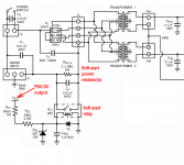
Another type of soft start circuit is advocated in Douglas Self's power amp book, and discussed thoroughly in National Semiconductor Application Note AN-1849. It puts a high wattage power resistor in series with the transformer primary for the first several hundred milliseconds after power-up, then shorts out the resistor with a relay. NSC's scheme is shown below.
NSC drives the relay from the output (secondary side) of the transformer. Others prefer to drive the relay from the input (primary side) of the transformer.
_
Attachments
NTCs are rude and crude, but give them some breathing room and a little goes a long way. (Doesn't too much R in the primary show up in the amp's output Z?)
If you were going to use a relay, you wouldn't use an NTC, you would use a fat resistor. I have some timer relays for when I go really big PS and actually need it, but for now, KISS.
Sniff around in that 555II and you might just find one already.
If you were going to use a relay, you wouldn't use an NTC, you would use a fat resistor. I have some timer relays for when I go really big PS and actually need it, but for now, KISS.
Sniff around in that 555II and you might just find one already.
I think that a worst case scenario is what you get when you only take into account the primary resistance, and turn on at the peak of the mains AC waveform. If you cover that case, you can rest assured that the turn on will be controlled for all conditions.
.
in case of big inductive load like a 50/60Hz toroidal transformer, the worst case scenario is turning on power at zero crossing of mains voltage. This looks a bit absurd, but can easyly be understood:
In that case the primary sees on half cycle with a corresponding voltsecond product twice as big compared to normal operation after setup with only 1/4 wave areas. And as voltsecond product is proportional to magnetic flux, the transformer is driven into saturation right from the start. Which explains big inrush currents even without massive capacitor banks on the secondary side.
I don't get it. For there to be any inductance there must be current flowing. It's an inductor's own magnetic field that causes resistance to current flow. But without any current flowing (before the system is turned on) the inductance is zero. So I don't see how transformer inductance can happen instantaneously. In fact I thought that it was the transformer's own magnetic field that increased impedance of the primary at 60Hz after it had reached "normal" operation and that it was the LACK of the magnetic field, and the fact the the primary of a high VA transformer was very low resistance, that was the underlying cause of inrush.
Can you (or someone) clarify these points please?
Diego Mike, if you are going to use an NTC then imho you need to try and competently size and install the NTC. As well as allowing an AC mains feed switch/circuit-breaker to better cope with all your equipment being turned on at once, the appropriate application of NTC's could allow the mains side fuse of each amp to be 'minimised' if it was initially over-rated to cope with the in-rush.
Sizing info is given in the NTC datasheets. One key sizing aspect is the in-rush joule rating of the NTC. Typically a datasheet provides an in-rush joule rating, or you need to calculate that from the generic use where mains AC voltage is rectified and directly charges a max capacitance level. You then need to assess the inrush joule heating through the NTC so as not to exceed its joule heating capability.
You appear to have two main in-rush contributors - the transformer primary winding, and the secondary side filter caps.
The filter caps need to be assessed with respect to the peak charging energy required at turn-on. As such, you need to know the amp's operating DC voltages, and the filter circuit configuration, and determine the capacitor stored joule rating.
A transformer's peak in-rush current characteristic will vary with lots of factors. Even if you had a storage cro and could make up a safe way to sample the mains current waveform, then you would need to take many many samples to appreciate the likely worst-case current characteristic. And then you would need to estimate what joule throughput that applies to the NTC. This would then become a worst-case level given that an NTC would lower the in-rush level.
An estimation of transformer in-rush that I've used is as follows. The transformer VA rating can be used to indicate the initial peak current level, and that current level can be compared to the peak mains current initially charging the capacitors, so as to obtain a ratio of peak currents. That ratio can then be applied to the capacitor joule level to give an estimate for the transformer inrush joule level. That may be a bit complicated for you, as I would normally use PSUD2 to estimate capacitor charging current (which requires transformer and capacitor and circuit details). If you are that way inclined, then although the link is about valve amp fusing, a section near the end on mains side fusing and NTC indicates the form of estimation that can be used.
https://www.dalmura.com.au/static/Valve%20amp%20fusing.pdf
If the worst case scenario gives an unrealistically high inrush then it could lead to choosing the wrong NTC or using an NTC when one is not needed. Perhaps an alternative worst case is to use the primary leakage inductance and assume turn on at zero crossing - see how that compares.CharlieLaub said:I think that a worst case scenario is what you get when you only take into account the primary resistance, and turn on at the peak of the mains AC waveform. If you cover that case, you can rest assured that the turn on will be controlled for all conditions.
No. Too much R in the primary shows up in the PSU's output impedance. This will only turn up in the amp's output impedance if no feedback is used. It may turn up in the amp's driving ability into low impedance loads, but this is not the same thing as output impedance.Andersonix said:Doesn't too much R in the primary show up in the amp's output Z?
No.CharlieLaub said:For there to be any inductance there must be current flowing.
Yes, you don't see it. Transformer inductance is a property of the transformer, not a property of the current. Hence it is present whatever the current.So I don't see how transformer inductance can happen instantaneously.
No. The very low resistance of a big transformer means that the initial DC transient lasts for longer (time constant is L/R) so the transformer may be pushed into saturation for longer. Even when in saturation, so with reduced inductance, it is likely that the transformer impedance will be dominated by inductance rather than resistance.In fact I thought that it was the transformer's own magnetic field that increased impedance of the primary at 60Hz after it had reached "normal" operation and that it was the LACK of the magnetic field, and the fact the the primary of a high VA transformer was very low resistance, that was the underlying cause of inrush.
Roughly, if you have a series L and R (where L dominates) and connect it across the mains voltage at zero crossing (the worst time to throw the switch) then you get two currents flowing:
1. the normal AC current, equal to V/(2 pi f L). You can calculate the rms current by using Vrms, or the peak current by using Vpk.
2. a decaying DC transient, which starts at a value equal to Vpk/(2 pi f L) and then decays with a time constant of L/R.
The net result (if R is small) is that half a cycle after switching on you get a current of nearly 2 x Vpk/(2 pi f L) - and this will almost certainly push the transformer into core saturation, thus reducing L and increasing the current further.
Temporarily boosting R (via an NTC or other soft start) means that this transient decays quickly, and might stop L from dominating. Killing off the transient keeps the transformer away from saturation so the peak current is within its design parameters.
Adding a secondary load complicates all this!
- Status
- This old topic is closed. If you want to reopen this topic, contact a moderator using the "Report Post" button.
- Home
- Design & Build
- Parts
- Selecting NTC Inrush Current Limiters