National Semiconductor / TI has an application note about building a high quality DC power supply for an audio power amplifier. It includes a soft start circuit that is simple and straightforward to understand.
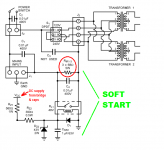
When the power is switched off, the DC supply rails which feed the amplifier ("VCC" and "VEE") are at zero volts. Because VCC is at zero volts, there is no current in the coil of relay RL1 and its contacts are open circuit.
Then when power is switched on, AC mains is applied to the primary of the power transformer(s) through 22.6 ohms of series resistance (68R parallel 68R parallel 68R). This series resistance prevents the inrush current from exceeding (Vmains / 22.6) = 5.3 amps in USA.
Since current is flowing in the transformer primary, current also flows in the transformer secondary. This secondary current passes through the bridge rectifiers and begins to charge up the filter capacitors on the DC supply rails VCC and VEE.
Eventually, the amplifier's positive DC rail voltage VCC rises high enough to pull-in the coil of 48V relay RL1. (Most 48VDC relay datasheets guarantee they will pull-in at 38.4VDC or higher.) This shorts out the 22.6 ohm resistance in series with the transformer primary, and the soft start is over.
image below.
Attachments
This is a good circuit but there is one small prob with it. If u very quickly cycle on/off, since the main caps will not have discharged, there is a chance the relay may stay engaged meaning there may not be any current limiting and that resistor will get extremely hot. I know such testing is rare but it may happen.
That is why I decided to use an independent timer (Airotronics MC1004531J) whose operation does not depend on the line voltage but a fixed time (I chose 2 seconds). It is still NOT foolproof but I anticipate the caps to be charged to a reasonable level after that time.
That is why I decided to use an independent timer (Airotronics MC1004531J) whose operation does not depend on the line voltage but a fixed time (I chose 2 seconds). It is still NOT foolproof but I anticipate the caps to be charged to a reasonable level after that time.
Hi Mark,
Using the secondary supply is the standard way most manufacturers work this. Some build a nice little timer. Using the DC supply to run the coil of the soft start relay is teh most direct way to do ths.
-Chris
Using the secondary supply is the standard way most manufacturers work this. Some build a nice little timer. Using the DC supply to run the coil of the soft start relay is teh most direct way to do ths.
-Chris
sorry I meant to say resistor will NOT be in circuit so it will NOT get hot but inrush current will not be limited. My bad....
Since free advice appears to be not working out very well, maybe it's now time to search for a circuit design consultant who specializes in this area, and pay nonzero money for expert opinion and advice. I don't know whether any of them take individuals rather than business firms as clients, nor do I know their dollars-per-hour consulting rates. But the people listed below are demonstrable and PUBLISHED experts, who certainly know how to solve your problem and how to do it your way. Whether they will take you as a consulting client or not, I have no idea.
Ben Duncan
Douglas Self
Christophe Basso
Paul Horowitz
Gabriel Alfonso Rincón-Mora
Michael Ellis
John Lenk
Ben Duncan
Douglas Self
Christophe Basso
Paul Horowitz
Gabriel Alfonso Rincón-Mora
Michael Ellis
John Lenk
I guess I initially started this thread with the hope I would find a PTC/posistor device, rather than using a resistor/NTC thermistor.
I was hoping that if somehow due to a fault, the relay did not engage, and the amp was used in a high input state, the inrush limiter posistor would heat up and INCREASE its resistance and therefore stabilise the circuit towards the lower current mode.
I could not find a posistor with such specifications.
Thanks for all your suggestions.
Hi cakyol,
There are good reasons why PTC resistors are not used in the classic sense that you are thinking of. However, there are PTC "fuses" or "breakers" that will open when a current limit is reached and reset automagically after they cool off. After they have tripped once their on resistance is slightly higher, but supposedly they don't degrade any further. This might be what you are looking for if you are thinking about fault currents. They obviously will not act as a surge limiter as your device would never be in a low current state.
Otherwise I would recommend that you look at some power amplifier schematics to see what actually works reliably. For starters, Marantz 500 and 510, 2500 and there must be others. Denon POA-6600 and others, Nakamichi PA-5 and PA-7 and the MKII versions. From that list you should be able to find enough proof for a certain circuit that it works well. If you are wondering about electronically limited power supplies, Look at Carvers more powerful amplifiers. A PM-1.5t or TFM-45 / TFM-55x schematic might really help there. This circuit was also found in the receivers with the darker metal finish, not the black ones. R-2000, R-1300 for example. The PM-2.0t uses a different power supply, but would also be good to examine.
Take your time and have a look at these. HiFiengine would be a good place to start.
-Chris
National Semiconductor / TI has an application note about building a high quality DC power supply for an audio power amplifier.
Hi Mark,
If you still have it in your browser history would you mind posting the link?
Thanks
Search Ti.com
AN-1849
(Audio Amplifier Power Supply Design)
A standard way to do a soft start (Pioneer did it this way for many models) is to use a high power resistor (3R3/20W) and have a thermal fuse (~109C) wired in series, placed underneath the power R, so they make contact.
Have this across the NO power relay contacts. Use a rectified/filtered DCV from the secondary to energize the relay coil thru the appropriate V drop R.
The thermal fuse acts as a safety device and will blow if there is a problem with supply for the relay.
Last edited:
I finally decided on the following components: airotronics MC1004531J (25 amp rating)
😱 🙂Brand new: lowest price $81.95
- Status
- Not open for further replies.
- Home
- Design & Build
- Parts
- Selecting NTC Inrush Current Limiters