Okay, listening started 9 hours ago and it continues... this amp is crazy good.
Everybody should have one 👍
Sorry if it's boring when I repeat it again and again, but facts are facts are facts 😍
Everybody should have one 👍
Sorry if it's boring when I repeat it again and again, but facts are facts are facts 😍

as Papa is sayin' - One on I'm working now .....
though, all (geez too many of them) on hiatus, these days finally started assembly of my own CNC precioussss coils winding apparatus
way to go boldly is to absolutely minimize outsourcing

though, all (geez too many of them) on hiatus, these days finally started assembly of my own CNC precioussss coils winding apparatus
way to go boldly is to absolutely minimize outsourcing
😁 😁 😁 😁these days finally started assembly of my own CNC precioussss coils winding apparatus
as Papa is sayin' - One on I'm working now .....
though, all (geez too many of them) on hiatus, these days finally started assembly of my own CNC precioussss coils winding apparatus
way to go boldly is to absolutely minimize outsourcing
View attachment 1219111

Guys, I need some help in decision making!
It's time to make a new amp!
Most of the parts are already acquired...except the PCB-s 😀
I have one pair of SJEP-s in stash, but now after reading this thread (once more time) I am puzzled and wondering if Scryer would be actually something I would be most happy with.
Previous amp was Babelfish 2J with Semisouth/IRFP and that was my favorite SS amplifier. Real magic from B2J would come with high efficiency loudspeakers.
I've also listened it with current loudspeakers (Falcon ls3/5a with subs), and it was nice, but 6c33c SET was little nicer with tone, bass punch and lush highs. B2J was more precise, bigger soundstage, more details...At the end I parted with B2J which new owner bought together with my previous loudspeakers.
I've listened SissySIT and it was not my cup of eardrops. It was too "thick" sounding but it also could be that the matching loudspeakers were not ok. It had nice "space" and stage positioning with that specific SIT magic but for me B2J was more tight, precise, faster and cleaner sounding but also with special character and tone, not exactly tube like but very nice nevertheless .
Is there someone (other than Zen, because he has no correct loudspeakers for evaluation 😀 ) who can make comparison for F8 vs Scryer, B2J vs Scryer or F8 vs B2J?
"...it's time to make a new amp..."
Yeah, for me too, I finished my last amp 2 days ago...
Yeah, for me too, I finished my last amp 2 days ago...
After 35+ hours of listening/burn in the amp becomes more and more fine, even more detailed, simply beautiful 😍
And it seems to fit my OB speakers perfectly👍
And it seems to fit my OB speakers perfectly👍

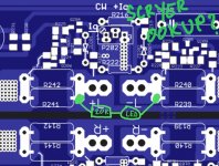
I may have made an ookup.
When I decided to add an LED to each board to show when power was on, I chose a potentially weird spot.
Is there a theoretical problem to having a resistor (20K) and LED connected from V+ to V-? It dawned on me that this may not be optimum, even though the amp has been running fine this way.
Do I need to change this so that the 20K-and-LED is connected from V+ to GND?
Attachments
I'm not sure if the relative "brightness" of an LED is linear to the current through it, but...
Just 2x as bright a LED if so...
Wait for wiser minds, but... I'd say... unless you're blinded, leave it alone.
Just 2x as bright a LED if so...
Wait for wiser minds, but... I'd say... unless you're blinded, leave it alone.
The original Aleph J was arranged that way, rail to rail. But the resistor value was much higher than yours.

I may have made an ookup.
When I decided to add an LED to each board to show when power was on, I chose a potentially weird spot.
Is there a theoretical problem to having a resistor (20K) and LED connected from V+ to V-? It dawned on me that this may not be optimum, even though the amp has been running fine this way.
Do I need to change this so that the 20K-and-LED is connected from V+ to GND?
all good - LED doesn't care haw you call rails given, as long polarity is proper ........ and also regarding the amp , no problem at all putting LED there
my Thumb of Rule is with nowadays LEDs - 1K per Volt, so - in this case anything from 33K to 47K will give you plenty of light
if you want more- decrease value of resistor
- Home
- Amplifiers
- Pass Labs
- Scryer ... or how F8 met Mighty SissySIT