
Thanks again Randy for the info - finally what value pot / attenuator did you use?
The marking on the pot knob looks great.
25k for both pot and attenuator.
You make a preamp jig using VFET F/E cards for gain stages.
...
Bulwark is installed now, and it's sounding great into my Aleph 30 monos and JBL4410 monitors. Test music is Eilen Jewell. I would have finished this build last night, but I saw her play a fantastic set.
Bravo!! Fantastic idea and brilliant execution. Good on ya.
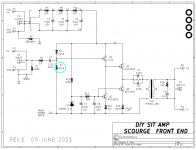
Scourge was originally designed to run from a +36V single ended power supply. With such a high supply voltage, ensuring symmetrical clipping was waaaaay down on the list of priorities. But if you cut the supply voltage in half, suddenly clipping behavior might become important.
An easy way to adjust clipping symmetry is to temporarily replace R7 with a 500K or 1 megohm trimpot, and then dial it up and down until the peaks and the troughs of a sine wave are clipped equally (on the oscilloscope). Then remove the pot, measure its resistance, and use a fixed resistor of that value (plus or minus ten percent) in the R7 position. Clean up the board and remove all flux residue; R7 is connected to a high impedance node that can't tolerate a lot of leakage current.
(Run the test using a low frequency sine wave like 200 Hertz, so the Zobel capacitor (C9) becomes a high impedance. Now you can't overheat the Zobel resistor (R16) even with a large amplitude, clipped waveform -- because C9 in series acts as a current limiter.)
_
Attachments
Which Antek donut did you use?So what do you do when you have:
- One pair of front end PCBs in your VFET amp
- Other pair(s) idle on the shelf
- A second system in the house
- Some time to experiment
You make a preamp jig using VFET F/E cards for gain stages.
I used an Antek donut, Salas SSLV1.3 UltraBiB shunt regulator (positive rail only) set to 36V, eBay chassis, a selector switch, and Alps pot. This build also encouraged me to get a ferrule crimper. Why did I wait so long for that nice tool?
Bulwark is installed now, and it's sounding great into my Aleph 30 monos and JBL4410 monitors. Test music is Eilen Jewell. I would have finished this build last night, but I saw her play a fantastic set.
Thanks
Which Antek donut did you use?
Thanks
AS-0532 - 50VA 32V and CA-050 Steel Cover
Hey MJ, I just bought all of your FEs for the V3, but I'm going to be using the dual die. I read about a change in the R for this option, but that was for the P? I need to read more and find out what I need to do for best results for both N&P versions.
A huge thanks for your design and those that sourced the parts for them, that is a huge deal, as those of us who have done it know. The price was fine, I didn't even think about sourcing the parts myself. I'm old, I might not have the time and damn sure don't have the inclination.
A huge thanks for your design and those that sourced the parts for them, that is a huge deal, as those of us who have done it know. The price was fine, I didn't even think about sourcing the parts myself. I'm old, I might not have the time and damn sure don't have the inclination.
Wrong thread I suspect. It sounds like you want to know more about the big ole power resistors on the output stage board, and what is Nelson Pass's recommendation / other builders' recommendation about changing these resistors or leaving them alone.
That's not really a Front End question and I, as designer of some of the Front Ends but not the VFET output stage(s), have no insight or opinion about the answer.
That's not really a Front End question and I, as designer of some of the Front Ends but not the VFET output stage(s), have no insight or opinion about the answer.
Well, I got the Scourge built, but haven't tested yet, I figure I'll build them all then test. This was an easy build and went fast.
Then I opened the Dread-naught box and started laughing. Well, this one won't be a drink while stuffing board. lol Damn, I'm glad I bought the kit version instead of hunting all that from a BOM.
A couple of the Scourge: I still need to deflux the top
Then I opened the Dread-naught box and started laughing. Well, this one won't be a drink while stuffing board. lol Damn, I'm glad I bought the kit version instead of hunting all that from a BOM.
A couple of the Scourge: I still need to deflux the top
Attachments
![20230309_133757[1].jpg](/community/data/attachments/1059/1059488-dce5843123e4b4bd7658b1600e6054e8.jpg?hash=3OWEMSPktL)
![20230309_134127[1].jpg](/community/data/attachments/1059/1059489-df13a7d06ed763e50c2fa9768fcd041c.jpg?hash=3xOn0G7XY-)
Member @pfarrell might offer his tips for remaining sane while building Dreadnought PCBs. What worked for me was to stuff 10 components, solder them, and clip the leads. Stuff, solder, and trim another 10 components. Then take a 45 minute break, and relax. Either do some more soldering that day, or wait till tomorrow.
Old eyes and tremors in my hands make it more difficult than it used to be. It looks like I will have the jewelers headband on for most of this one. pfarrell did some amazing work on his builds, it looked like a factory robotic job it was so good.
I work as you say, I put a number of parts on solder them trim and then stuff some more working from smallest to largest usually. I like to start with the R and small stuff that way you can remove the flux before the board gets busy. I didn't do that with Scourge, old brain too. 😛
I don't know how you did the layout Mark it must have been a nightmare to get done.
Thanks again for all you do.
JT
Thanks @thompsontechs. I take my time, worked in sections as Mark does/suggests. Smallest to tallest components. I tend to use high heat and a not particularly small tip on the Hakko, kinda hot and fast theory. I find getting flux off the top of the board to never come out perfect, so I aim for a perfect top joint from the bottom. Occasionally I'll have to spot a top pad, probably not needed—but OCD, if there's some massive ground plane action that really sucks the heat. Basically I find the "work" to be pure bliss—so stress isn't really a thing for me personally, here.
I loved building these boards! I wish it made sense to build them again. 😛
I've had to satisfy the itch with at least 10 guitar tube amp builds...having reached a certain level of awesome in the hi-fi system. And alas, VFet monos still need to be finished! It WILL happen! All chassis work at this point.
As for flowing them from the backside only, that is possible because Mark used bigger holes, which allows for a number of diff parts, but also lets the solder flow through the boards better. IMO, it's critical for multi-layer boards especially to do so. When it comes to caps and large components that prevent one from flowing from the top side as well. Yes the holes have copper too, but I wonder how thick it is, and if it will hold the current as well as a trace.
From a solder jockey like me, I really appreciate the thought, and attention to detail in these boards.
I also work with a hot iron chisel type and try to get it on and off quickly, as the longer you are on the more flux burns off and stops the flow. In fact, I had a bad tip with the last board and had to use a smaller one, it was more difficult to work with by far. I have since got a new one.
When you get back to it please post up some nice photos of the work, I always like looking at the results from those who do it well.
Did you post links to some of your tube amp work? If so post a couple links privately if you would.
JT
Bigger holes make it much easier to unsolder and remove / replace components. Which seems like an important attribute, given that DIYers are stuffing and soldering the boards.
Last edited:
Much like Maniraj previously mentioned, I had a pair of Scourge boards built up and sitting so I Decided to make a preamp/front end jig myself. I have a set of Mofo's that seemed an ideal match. Using extra bits I had about it all came together. (Wood chassis with Aluminum pieces to mount connectors, alps pot, SMPS filter from DIYAudio store)
Not being especially happy with the 36v offbrand Laptop supply from Amazon and not having a Salas or sigma11 type regulated supply currently on hand. I thought I would be smart and battery power it (two 18v drill batteries in series did the trick).
However I'm picking up a bunch of noise. It appears to be 2mv peak to peak sawtooth at I'm guessing 120hz with some higher frequency garbage mixed in (sorry I didn't pay more exact attention to the frequency ranges yet) Will need to pull the scope back out and be more exact on the frequencies later.
Of note:
1. Noise appears constant / not changing with volume.
2. The DC input connector is metal so it connects V- to the aluminum bracket. (This concerns me somewhat....not sure though )
3. All other input/output connections are not conducting to the brackets
4. Jumped all input wiring and did 1" connections straight to input. .... No help same noise.
5. Tried a CL60 between V- and Earth Grounded surface....No Help same noise.
6. Tried covering the Edcore with some makeshift metal shielding....No Help or any change noticed.
7.Both channels are behaving the same.
8. If I turn the volume up enough to swamp out the noise , the boards appear to be functioning just fine.
I have an Antek 28v on hand that should do the trick...if I decide to do a more traditional build ( Suuply/Regulator/Aluminum chassis earth grounded with Audio Ground lift seperate). Haven't decided to go through with this yet.
My gut says I have created a ground loop somehow.
Any ideas ?
Find the noise freq first. Since you went DC with the supply and have, what you think, is 120/2 60Hz then, I would say perhaps a grounding issue with some intrusion from AC, but find the actual freq first.
- Home
- Amplifiers
- Pass Labs
- Scourge, Bulwark, Marauder, Dreadnought "front end" cards for DIY VFET amp