So your power supply network, including the DC to DC booster, seems to be working correctly. Congratulations! That's more than half the board which is good news.
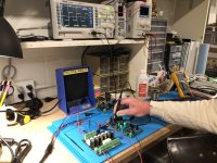
Finding trouble with the signal path will require, unsurprisingly, studying signals. Which means: with an oscilloscope.
Finding trouble with the signal path will require, unsurprisingly, studying signals. Which means: with an oscilloscope.
Okay, I put a 120k load resistor at the output. At some point I must have mixed a 120 in with some 120k parts. I did measure, it, but failed to detect my error. I'm thinking that might have been after cocktail hour, at least that's my story and I'm sticking to it.
Sorry for taking up your, valuable, time on such a dumb mistake Mark.
~Bows head in shame~
Sorry for taking up your, valuable, time on such a dumb mistake Mark.
~Bows head in shame~

Easy to miss simple stuff...You could be staring at color bands of THE problem part yet not see it because your brain is worrying over something more complicated that has nothing to do with the real issue.
I know the feeling...
I know the feeling...
They both presented the same, so it looks good; I'll confirm the second tomorrow. I'm confident both are going to be fine.
Thanks again for you help.
On to the BW!
JT
Thanks again for you help.
On to the BW!
JT
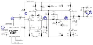
BULWARK CIRCUIT
Bulwark takes the basic circuit design of a preamp that Nelson Pass designed in the middle 1970s, and applies two modifications: (1) instead of a single ended input stage plus an opamp DC servo, Bulwark uses a differential input stage and no DC servo. (2) Bulwark flips the circuit upside down: what was NPN is now PNP and vice versa.
Bulwark uses the same cute bootstrap circuit (Q6 + R18) to raise the effective AC collector load on Q4, to extremely high impedance levels. This means that Q4 has extremely high gain. And since Q6 is an emitter follower, the output impedance which drives the transformer primary, is quite low.
R22, R21, and C10 allow for future modifications if the builder so desires. Besides the 5X gain provided by the Edcor transformer, suitable values of R22 and R21 can be installed to increase the gain further. If desired.
I get it, so R22 needs a short unless you want more gain and then the three would be adjusted and stuffed. If not DNS (Do not Stuff/Install) R21 and C10 and short R22. I know it was posted previously somewhere and it finally clicked.
![20230424_144642[1].jpg](/community/data/attachments/1075/1075883-5d2cfb023bb5dea9d535757659ce3f2d.jpg?hash=XSz7Aju13q)
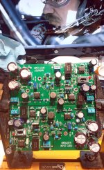
Props to Mark on the layout... did JP work on the layout Mark? It looks like his work, it's that good. If not stellar work down to the screw marking for the VR on the PCB. It's so well done you can verify the right part by looking at the PCB as the part is stamped there. Always double check, but that was very handy. All I need do is some last bit of solder work and testing. All four will be tried and then the whole thing will be sent to a friend for him to test and listen. After that we will compare notes.
Thanks for the kind words!!
I laid out all of the PCBs for the entire Theseus project (amp channels L&R, PSU filter, Tuba filter, Scourge, Bulwark, Marauder, Dreadnought, Relentless, Nimitz, Missouri, Bon Homme Richard, Lexington, Kitty Hawk, Hornet, Pequod), by myself. The higher density boards (greatest number of parts per sq inch of PCB) use vertically mounted "soldier" resistors; the low density ones have conventional, flat mounted resistors. Bulwark was in the latter category. The friends-and-family-only card "Relentless" is SMD except for the Edcor and the Euroblox wire-to-board connectors.
I laid out all of the PCBs for the entire Theseus project (amp channels L&R, PSU filter, Tuba filter, Scourge, Bulwark, Marauder, Dreadnought, Relentless, Nimitz, Missouri, Bon Homme Richard, Lexington, Kitty Hawk, Hornet, Pequod), by myself. The higher density boards (greatest number of parts per sq inch of PCB) use vertically mounted "soldier" resistors; the low density ones have conventional, flat mounted resistors. Bulwark was in the latter category. The friends-and-family-only card "Relentless" is SMD except for the Edcor and the Euroblox wire-to-board connectors.
Last edited:
Really outstanding work here Mark. I can only imagine the number of hours involved. I'm excited to give them a listen. I need to build Pops original too. does anyone have those available, or do I need to have some made?
Marauder is a fun one. After you’ve had some time with it, try substituting the OPA445 for the OPA552. The JFET input gives it a different sound.
Remembering of course that the signal passes through one (sometimes two!) OPA2134s before being amplified yet further by the OPA552. Depends on the setting of the polarity inversion slide switch. Fortunately the OPA2134 chip is socketed too, and you can fiddle-fornicate around with other possibilities for the 2134 socket, including Sparkos discrete opamps, if you so desire. There's plenty of love here on diyAudio for the OPA1656 + SMD-to-DIP adapter, to name a second example. OPA1656 has MOSFET inputs, so, if your personal voodoo hinges upon input device fabrication technology, that makes yet one more contestant in the bake off.
Last edited:
All 4 sets done and tested okay, just need to build the box and get the VFETs in to start listening.
I am finally getting around to finishing my Ship of Theseus. The PFILT is done and tested. The Dreadnought is done, tested and aligned to 50khz. The Missouri is done - can’t wait to play with the balanced input on that one. And I have the amp modules built. Now I need a chassis, probably a 4U Deluxe from the store. I still have a Bulwark kit to build, but I’m going to wait to hear what I have built so far before putting that one together...
This is a great project Mark! Thanks again for your generosity in making all of this available in its various forms (Through the store and from the downloadable Gerbers)!!


This is a great project Mark! Thanks again for your generosity in making all of this available in its various forms (Through the store and from the downloadable Gerbers)!!
Attachments
Last edited:
- Home
- Amplifiers
- Pass Labs
- Scourge, Bulwark, Marauder, Dreadnought "front end" cards for DIY VFET amp