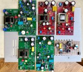
Congrats to Derek for completing a matched set 
I'm finishing up a pair of Marauder boards. Taking my time to make sure all the tiny parts go in the right places. I needed to use my old Wavetek DMM to sort the tiny ceramic pF capacitors. Written labels on the 47 pF, 68 pF and 1000 pF parts would be very helpful.
I'm finishing up a pair of Marauder boards. Taking my time to make sure all the tiny parts go in the right places. I needed to use my old Wavetek DMM to sort the tiny ceramic pF capacitors. Written labels on the 47 pF, 68 pF and 1000 pF parts would be very helpful.
Pass DIY Addict
Joined 2000
Paid Member
For measuring the little pF caps, and everything else…
https://www.amazon.com/Mega328-Digital-Transistor-Resistance-Capacitance/dp/B07WT9VVZB
It’s the best $13 you can spend on this hobby.
https://www.amazon.com/Mega328-Digital-Transistor-Resistance-Capacitance/dp/B07WT9VVZB
It’s the best $13 you can spend on this hobby.
Many thanks everyone. But your cheers may turn to jeers on learning that I backwards installed a 100 uf 100V polarized cap at position C19 on one of the Marauder boards. 😱
Fortunately, I caught the mistake before the cap popped - but it's definitely bulging. Replacement has been ordered. I'm hoping that C19 just does ripple/noise filtering duty and that having it backwards cap didn't harm any of the other components. It had no apparent effect on the circuit's ability to amplify a signal, nor on setting the JBoost frequency to 50kHz.
cheers, Derek
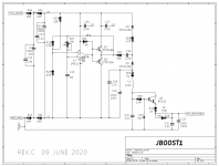
See Marauder schematic attached below.
Electrolytic capacitor C19 is indeed a noise filter / bypass capacitor. If you accidentally install it backwards, that loads down the DC-to-DC converter pretty severely. So don't run the board with backwards C19 for very many seconds.
I think if you simply remove it and replace with a brand new and good capacitor, you and your Marauder will probably be just fine.
_
Attachments

Many thanks again Mark.
Just to be sure, I think I may replace Q1, Q2 and the LM311 before putting the board to use.
cheers, Derek
Just to be sure, I think I may replace Q1, Q2 and the LM311 before putting the board to use.
cheers, Derek
A new pair of Marauder boards are up and running. Dialed in to 50.0 kHz at the output of the LM311, no smoke, happy so far. 🙂
Will swap them into my VFET amp in a little while, replacing the Scourge boards that I was listening to yesterday while completing assembly.
Will swap them into my VFET amp in a little while, replacing the Scourge boards that I was listening to yesterday while completing assembly.
A couple of decades ago I read a review of an AC mains power regenerator, in either Stereophile or The Absolute Sound magazine. It had a knob and dial on the front panel which let you adjust the frequency of its "perfect sinewave" output. The reviewer dutifully tried it out at a bunch of different settings and concluded that yes indeed, the downstream equipment produced the best sound when given AC sinewaves at 66 Hertz. Not 60 Hertz.
Who knows, a similar effect might occur in Marauder and/or Dreadnought too. Maybe running the DC-to-DC converters at another frequency besides 50 kilohertz, might produce the best sonics. It would be a bit of a surprising outcome, but who knows, maybe it could happen. Pretty easy experiment too, for anyone who feels like giving it a try.
Who knows, a similar effect might occur in Marauder and/or Dreadnought too. Maybe running the DC-to-DC converters at another frequency besides 50 kilohertz, might produce the best sonics. It would be a bit of a surprising outcome, but who knows, maybe it could happen. Pretty easy experiment too, for anyone who feels like giving it a try.
Pass DIY Addict
Joined 2000
Paid Member
My wife said she needs a Christmas gift idea for me, so I just ordered a set of Bulwark cards and a set of PSU filter cards to go with them for my P-ch vFet amp. 
I'll have to sit on them for a while before being able to listen, though.
I'll have to sit on them for a while before being able to listen, though.
Last edited:
Notes on JBOOST1D
This sub-circuit is shared by the Dreadnought and Marauder cards. It is responsible for DC-DC conversion of the nominal 36V VFET amp supply voltage to approximately 58V (maybe a little less) to drive the front end gain circuits of those two cards. Without an Edcor signal transformer to provide voltage gain, the gain circuits themselves need to provide a wider voltage swing to drive the VFET output stage to full power.
The switching frequency of the DC-DC converter is determined by adjusting the R25 trimmer resistor (potentiometer) in conjunction with the value of C14, normally 1000 pF. There is a fairly wide range of frequency adjustment available, especially if one changes the value of C14. The instructions call for setting the switching frequency to 50 kHz. This appears to be a perfectly adequate value, and seems to do the best job at providing the maximum output voltage on the POS_BOOSTED rail.
Out of curiosity, and as suggested by Mark J., I tried a few other frequencies to see how they might affect performance. With C14 left at 1000 pF, it is possible to get 55 kHz, and as a stretch, 77 kHz. I used the Dreadnought cards as my test bed, so all reference designators are relative to that design. The basic output can be measured ad the junction of R30 and D7. This is somewhat higher than the POS_BOOSTED voltage, and depends on the load current. Neither 55 kHz nor 77 kHz gave a significant increase in voltage at this node. Perhaps 0.02V, but this would be subject to loading. Measuring the voltage of POS_BOOSTED gave smaller voltage increases.
After changing C14 to 330 pF, it was easier to set the switching frequency to 77 kHz, as well as 100 kHz and even 120 kHz. The 100 kHz frequency behaved much as 77 kHz. Going up to 120 kHz started to reduce the output voltage. Probing the output of the LM311 revealed that it was showing signs of slew rate limiting on the rising edges. Thus there was less energy being fed into the RLC circuit formed by R30, L1 and C20. The output as driven by Q11 and fed through R32 and L2 is just being filtered to reduce vestigial amounts of the switching frequency.
With the switching frequency set back to the recommended 50 kHz, I tried a couple other tweaks to lower the residual noise. First I increased L1 to 220 uH. This lowers the higher harmonics of the switching residual, but has little effect on the peak value of the noise. When measuring POS_BOOSTED with a Fluke 101 multimeter on its AC mV range, there is little difference – perhaps a reduction from 300mV to 298mV.
The other thing to try is increasing the value of C20 from 2.2uF to 10uF. Given the necessary 100V rating for this part, it is difficult to find small electrolytics of higher value that will still easily fit on the board. This seems to have a greater impact on the higher order components of the residual noise, but again only a small effect on the overall AC mV reading at POS_BOOSTED.
So is this a worthwhile tweak? I would say yes to dropping a 10uF, 100V into location C20. This is because the PSRR of the OPA552 used by the Marauder cards decreases noticeably with frequency, as does that of the Dreadnought gain circuit. With just the 10uF capacitor tweak, the Marauder cards seem to have benefited in detail and stereo imaging. And by a noticeable amount. It's an easy thing to try, and doesn't cause any harm.
I will do further listening tests with my Dreadnought cards later on.

Classical slew rate limiting occurs in opamps, when the input diff pair's constant current source is completely, 100 percent steered to one side or the other, charging the internal compensation capacitor with 100% of the available current. Then
and in the opamp case, "I" is 100% of the tail current, "C" is the internal compensation capacitor value, and "dV/dt" is the slew rate.
Voltage comparators ICs like the LM311, on the other hand, don't have internal compensation capacitors and don't exhibit classical slew rate limiting. Instead they are one-bit analog to digital converters, and their final output stage is a plain ordinary digital gate which operates at the same speed as other ordinary digital gates. For board design flexibility, the output stage is usually an open collector digital logic gate, as on the LM311. Rise time of the output pin is completely determined by circuitry outside the IC, and not by an internal CCS charging an internal capacitor.
_
- I = C * dV/dt
and in the opamp case, "I" is 100% of the tail current, "C" is the internal compensation capacitor value, and "dV/dt" is the slew rate.
Voltage comparators ICs like the LM311, on the other hand, don't have internal compensation capacitors and don't exhibit classical slew rate limiting. Instead they are one-bit analog to digital converters, and their final output stage is a plain ordinary digital gate which operates at the same speed as other ordinary digital gates. For board design flexibility, the output stage is usually an open collector digital logic gate, as on the LM311. Rise time of the output pin is completely determined by circuitry outside the IC, and not by an internal CCS charging an internal capacitor.
_
Attachments

Huh, wrong term for the observation. There was actually a bit of a ‘knee’ to the rising edge, so perhaps I should have guessed a different mechanism was at work.
It's quite possible that one particular setting of the LM311's square wave frequency, gives greater perceived listening enjoyment than all other settings. A bit of experimentation (post 288) might yield huge benefits -- at zero cost. No test equipment is required, no meters need to be read. Just use your handy Bourns H-90 trimmer tool . . . . and please remember to remove its metal clip!

Maruader cards are up and running. Setting scope to do frequency count made finding 50kHz a snap. I'm running the amp on my horns now and I'm really enjoying the sound. It seems to throw a huge soundstage with really nice space around instruments. I played the requisite test tracks - now I'm on to some fun rock'n'roll.
I finished my Bulwark boards today, too. I'll swap those in after some runtime on the Marauder cards.
Excellent work Mark - a huge THANK YOU for your efforts on these front end boards!!!!
I finished my Bulwark boards today, too. I'll swap those in after some runtime on the Marauder cards.
Excellent work Mark - a huge THANK YOU for your efforts on these front end boards!!!!
The Marauder and Bulwark cards have become my favorites. It’s fun to see others starting to enjoy them as well.
Congratulations @rhthatcher on a successful build! You'll have enormous amounts of fun with these. And you can ponder weighty questions such as "Do the front-ends with Edcor transformers sound different than the transformer-less front ends?" Or, "Do I hear any difference at all, when I configure the card as Inverting versus NonInverting?" Or perhaps even "What's the sonic difference between setting Marauder for 35 kHz versus 50 kHz versus 65 kHz?" Save that last one for a gloomy rainy day when you can think of absolutely nothing else productive to do with yourself.
The last iteration of my Dreadnought cards have reached a stable tonal balance after an extended run-in period.
For a while, I used these as a test bed for trying different options for the JBOOST power circuit. They are now running with a switching frequency of 78 kHz. This seems to be a good option according to my scope, but I’m not certain I can hear anything definitive from this.
The last audible change that I made was to replace the output coupling capacitor with an Elna Silmic 100 uF, 50, bypassed by a 0.47uF, 63V PET film cap. This is the bit that needed a longer run-in. It is a combination that worked well on a couple other cards that I built. Of course great care is needed to install the polar cap in the correct orientation. The final sound is smooth and well balanced. Perhaps not as “fast” as the Marauder card, but very enjoyable to listen to.
Marauder HV2
I am planning to use the Marauder and Dreadnought cards to drive other unity gain amplifier stages of intermediate power. One example is the 2SK180 Tokin Follower in choke-loaded common drain configuration. Since the various Tokin follower amps tend to run from a single rail of 28V to 32V, and I wish to drive them to full power, I wanted to ensure that the voltage booster circuit could deliver sufficient voltage from a lower supply input.
I have been able to tweak the JBOOST circuit to provide about 55V on the POS_BOOSTED rail from a 28V input. The primary means of achieving this is to replace R28 with a 22 Ohm resistor. I also replaced L1 with a 510 uH inductor (DCR of 10 OHms), and C21 with a 10 uF, 100V electrolytic cap, Finally I replaced D10 with tighter precision version, the BZX85B62.
There is one caveat: When the FE card is supplied with the original 36V, the boosted power rail runs at 59.5V, which is a tad higher than the OPA552 is happy with. So the solution for that scenario was to replace the OPA552 with an OPA445. This makes for a wonderful combination, one which I may prefer to the OPA552 running at the stock 58V.
You could replace the darlington transistor in the output smoother portion, with a high beta singleton like the Sanken** 2SC3852. This will eliminate one VBE drop and raise the output DC voltage by one VBE. You could also shop around for Schottky diodes with lower max-reverse-voltage specs; the ones in the Marauder Rev.C schematics have a giant safety margin built in: they're 150V whereas you need less than 65V. Lower reverse voltage diodes will have lower forward voltage, and since there are two diodes in series, every 0.1V of Vfwd improvement gives 0.2V of output voltage increase. You could also replace Q1 and Q2 (rated for 0.5A continuous collector current) with some of the Zetex devices rated for 3.5A in a TO-92 package. 3.5A transistors will have dramatically larger emitter-base junction area, thus lower VBE, than 0.5A devices. Again every 0.1V of improvement gives 0.2V of higher output voltage. Watch out for base current though; the big devices will have alarmingly smaller Beta than the 696B/795A in Marauder.
There's an excellent chance you'll experience a big Aha! Moment, if you measure the differential DC voltage between nodes "S3" and "G3" in the Marauder DC-to-DC converter. Node S3 is accessible by a crocodile clip on the flying-lead anode of diode D8. Node G3 is accessible by a crocodile clip on the flying-lead of resistor R23.
Mouser doesn't carry Sanken** products, but DigiKey does.
_
Attachments
- Home
- Amplifiers
- Pass Labs
- Scourge, Bulwark, Marauder, Dreadnought "front end" cards for DIY VFET amp